Assembly Cut
Cuts one profile, a rectangle, a circle or a polygon on a sketch plane, through the components you pick, right in the assembly. Use it for a slot, a hole or a pocket that has to go through several parts that sit together, like a cable slot through a plate and the block on top of it. Only the parts you pick are cut. Each one keeps the cut as a step at the end of its own History, saved as a new version of that part. Assemblies need the Pro plan, and cutting needs the modeling tools of your plan.
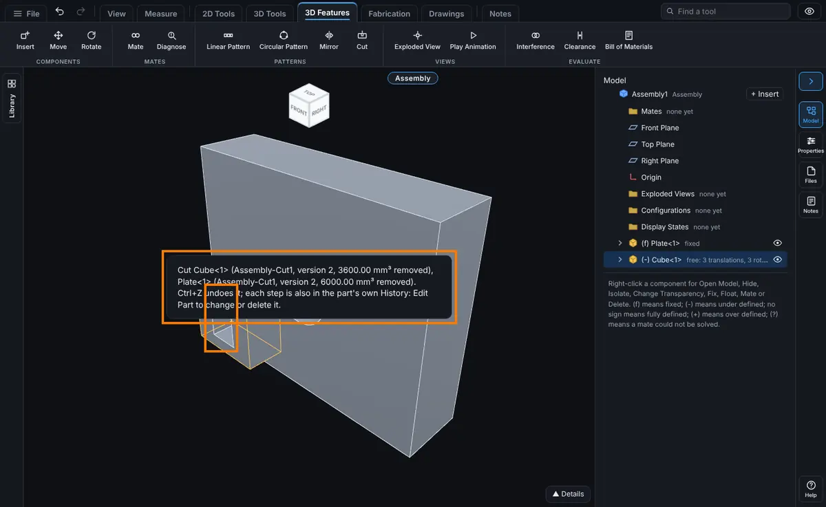
What you get: each picked part cut by the same profile, in one go. The message says how much was taken from each part, for example "Cut Plate<1> (Assembly-Cut1, version 2, 6000.00 mm³ removed)". Every part gets a History step named Assembly-Cut1 (then Assembly-Cut2, and so on) that you can edit, suppress or delete later with Edit Part. The cut is saved in the parts, so it is there when the assembly or the part is opened again. Ctrl+Z undoes the whole cut in one step.
When to Use It
- Cut a slot or a hole through two or more parts that are stacked or clamped together, so they line up
- Cut a pocket in one part at a place you can see best in the assembly
- Trim parts that run into a frame, by cutting them all with one profile
Step by Step
- Open an assembly that holds the parts to cut (see Assemblies: Start and Insert Parts). The parts must be saved models of your own, in STEP.
- Pick one of the parts, then open the window in either of these ways:
- Click Cut in the Patterns group of the Features tab, beside Mirror.
- Right-click the component, then choose Assembly tools, Assembly Cut...
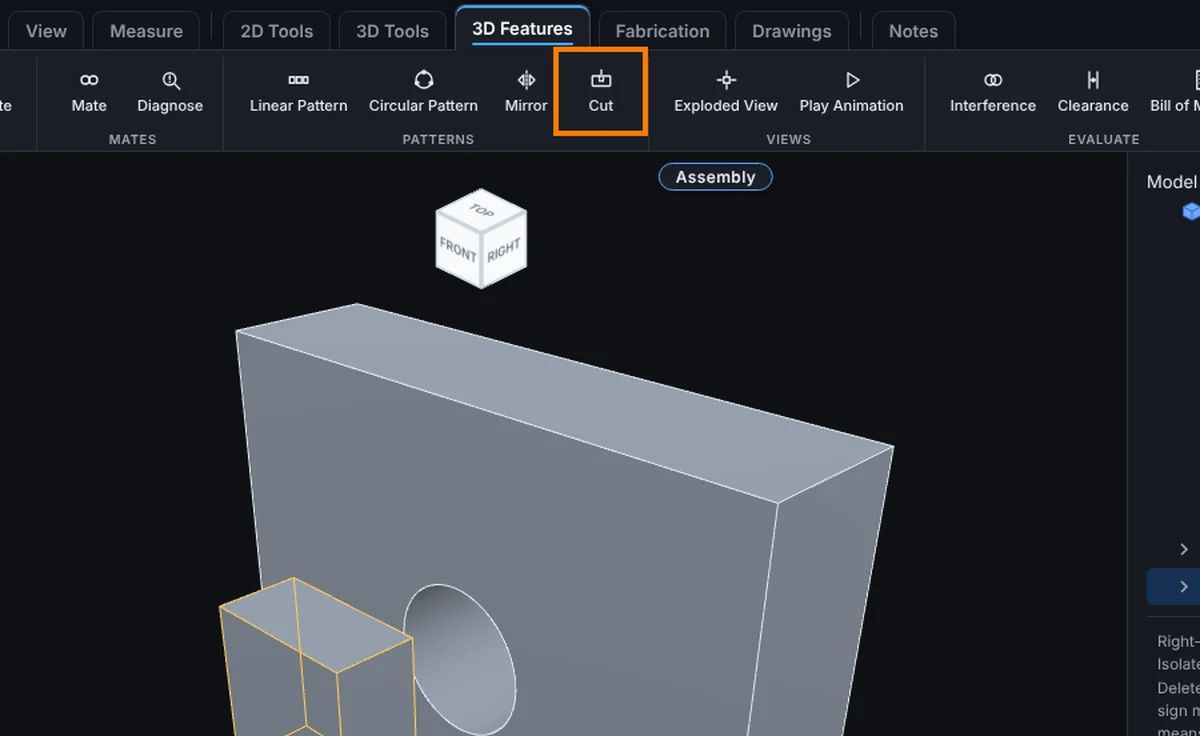
- The Assembly Cut window opens. The part you picked is already under Components to Cut. To add more, click Pick in the view or the tree, then click each part in the view or in the Model tree. Click the x beside a name to take it out of the list.
- Under Sketch Plane, click Front Plane, Top Plane or Right Plane (planes through the assembly origin), or click Pick a flat face and then click a flat face of any component. The line under the buttons reads "Plane: ..." and names the plane in use. Type an Offset to move the plane along its own direction, for example 5 or 1/4 in.
- Under Profile, choose the Shape:
- Rectangle: type Centre X, Centre Y, Width and Height.
- Circle: type Centre X, Centre Y and Diameter.
- Polygon: type the Corners as X, Y pairs split by semicolons, in order around the outline, like 0, 0; 40, 0; 40, 20.
The line under the boxes says where X and Y are measured from and which way they run, for example "Measured from the assembly origin: X runs along the assembly +X, Y along +Y."
- Under End, choose Through All to cut through the whole part, or Blind and type a Depth. Choose the Direction: Forward, Reverse or Both ways.
- Watch the blue outline in the view. It shows the profile on the plane and how far the cut goes. Change a box and it moves at once.
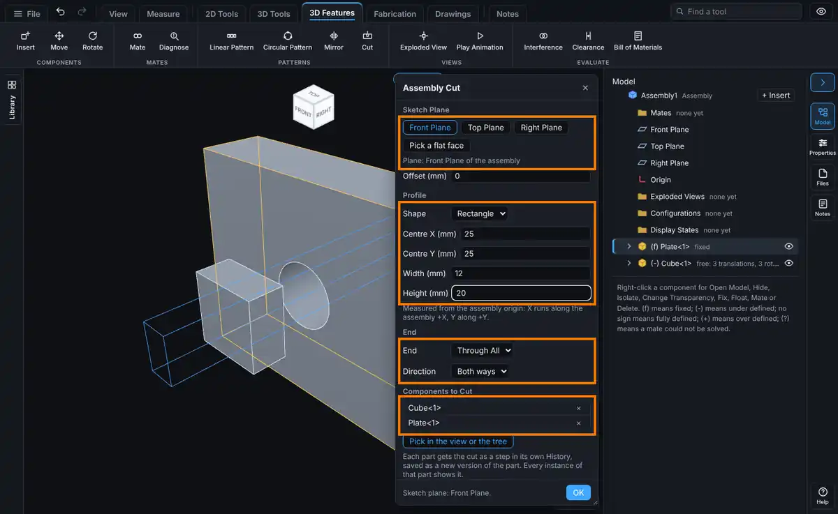
- Click OK. The window says "Cutting..." while the modeling engine cuts each part. When it is done the window closes, the parts show the cut, and a message names each part, its new step, its new version and how much was removed.
Options
| Option | What it does |
|---|---|
| Front Plane, Top Plane, Right Plane | Sketches on that plane of the assembly origin. X and Y are measured from the origin. |
| Pick a flat face | Turns on picking: click a flat face of a component. X and Y are measured from the middle of that face. The plane follows the component if it moves before you click OK. |
| Offset | Moves the sketch plane along its own direction by this much. A plus value moves it the way the plane faces (out of a picked face). 0 is the default. |
| Shape | Rectangle (the default, 20 by 20), Circle or Polygon. |
| Centre X, Centre Y | Where the middle of a rectangle or circle sits on the sketch plane. |
| Width, Height, Diameter | The size of the rectangle or circle. More than 0 and up to 100 m. |
| Corners | The corners of a polygon, 3 to 200 of them, as X, Y pairs split by semicolons. |
| End: Through All | Cuts through the whole of every picked part, however thick it is. This is the default. |
| End: Blind | Cuts only as deep as the Depth you type. |
| Direction: Forward | Cuts from the plane away from the way it faces: into the part for a picked face, toward the back for Front Plane. The default. |
| Direction: Reverse | Cuts the other way. |
| Direction: Both ways | Cuts to both sides of the plane. With Blind, half the depth goes each way. |
| Components to Cut | The parts to cut. Up to 20 at a time. |
| Pick in the view or the tree | Turns on picking: click a part to add it. Click the button again to stop. |
| OK | Cuts every part in the list and saves each one as a new version. |
Boxes take any unit, like 25, 1 in or 1/2 in. A number with no unit is in the assembly's unit.
Change or Undo the Cut
Right after a cut, press Ctrl+Z (or click Undo) in the assembly. The whole cut is one step: every part it cut gets a new version holding its earlier file and History, and the mates go back as they were. Ctrl+Y (Redo) cuts them again, the same way. Undo and Redo work newest first, together with moves, mates and every other change in the assembly, and a new change clears Redo.
Later on, the cut is a normal step in each part's History, so you change it in the part.
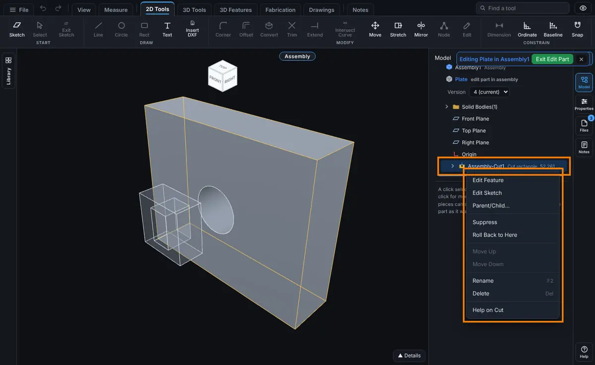
- Pick a part that was cut and open it with Edit Part (right-click it, Edit Part). Its History shows the Assembly-Cut1 step at the end.
- Right-click Assembly-Cut1 to see what you can do with it:
- Edit Feature changes the depth, the end or the direction.
- Edit Sketch changes the profile.
- Suppress turns the cut off but keeps it.
- Delete takes the cut out of this part.
- Click Exit Edit Part. A new version of the part is saved, and the assembly shows it.
Each part is changed on its own. To take the cut out of every part, do this for each of them.
Tips
- Nothing is saved until every part has been cut. If the engine cannot cut one of them, none of them is changed, and the message says which part and why.
- If the server refuses to save one part, every part saved before it is put back at once (a new version holding its earlier file), and the message says so.
- Each part is cut as its newest saved version. If the assembly showed an older version of a part, it shows the newest one, cut, afterwards.
- Through All is kept in the part's History as a cut deep enough to pass right through the part as it was. Edit Feature shows it as Blind with that depth, as the sketch tools' own Through All does.
- Every cut, Undo and Redo adds a version to each part it changes, so the part's version list shows each step.
- Every placed copy of a cut part shows the cut, because they are all the same saved model. Other assemblies that use the part show the "Parts changed" bar next time they open.
- Mates keep working. A mate on a face the cut took away turns red, and the message says so. See Mates: Fixing Mate Problems.
- Use Through All with Both ways when you are not sure which side of the plane the parts are on.
- A cut that ends up partly outside a part is fine. Only the part that lies inside the profile is taken away.
Limits
- The profile is typed into the window: a rectangle, a circle or a polygon. Drawing it with the sketch tools in the assembly is not available yet, and the profile cannot follow the edges of another part (no references between parts).
- The cut is not tied to the assembly. If you move a part after cutting it, the cut moves with the part, not with the other parts. It is not aligned to holes in other parts for you.
- The cut is saved in each part's own STEP file. There is one file per part, so every copy of that part in every assembly shows the cut. To cut only one copy, save the part as a new model first and use Replace Components.
- Only parts saved as STEP models of your own can be cut. A pattern instance, a part inside a subassembly, a hidden part and a frozen copy cannot.
- Up to 20 components at a time. A part file over 64 MB, or one with more than 200 bodies, is refused.
- One go of cutting has 60 seconds for all its parts together. The clock is looked at between the engine's steps, so a single long step can run a little past it. When the time is up, the cut stops and nothing is saved.
Common Mistakes and Messages
- "Pick one or more components to cut first." The list is empty. Click Pick in the view or the tree and click a part.
- "Pick a sketch plane first: Front, Top or Right Plane, or a flat face." Choose the plane.
- "That is not a flat face. Pick a flat face, or Front, Top or Right Plane." What you clicked is round or not a face.
- "The face the sketch plane came from is gone. Pick the plane again."
- "... is not touched by the cut: the sketch does not reach it. Move the sketch or change the direction, or take ... out of the list." The profile misses that part. Check the blue outline, change Centre X and Centre Y, choose Both ways, or take the part out.
- "The cut would take away all of ..., leaving nothing. Make the sketch smaller, or use a depth."
- "... took too long and was stopped. Cut fewer or simpler parts, or use a simpler sketch." or "Cutting took more than 60 seconds and was stopped. Nothing was saved. Cut fewer or simpler parts, or use a simpler sketch." The 60 second limit for the whole go was reached. Nothing was saved.
- "... is hidden. Show it first (right-click it in the Model tree, Show), then pick it." A hidden or suppressed part is not cut.
- "... is a frozen copy (its saved model was deleted), so it cannot be cut. Replace it with a saved model first." See Replace Components.
- "... belongs to another account, so it cannot be cut here."
- "This assembly is shared with you to view only. Its parts cannot be cut."
- "... and ... are the same saved model, so one cut through both would cut that part twice. Pick one of them." Two copies of one part are in the list. Keep one: the cut shows on every copy.
- "That is an instance of a pattern. Cut its seed: the instances show the same part."
- "A part of a subassembly cannot be cut from here. Open the subassembly and cut it there."
- "Assembly Cut takes up to 20 components at a time. Cut the rest in a second go."
- "Width: type a size more than 0 and at most 100 m, like 25 or 1 in." A size box is empty, 0, below 0 or not a number. The same message names Height, Diameter or Depth.
- "Corners: type at least 3 corners as X, Y pairs split by semicolons, like 0, 0; 40, 0; 40, 20." Other Corners messages say two corners are in one place, the sides cross, or the corners lie on one line.
- "... has its History rolled back (the rollback bar is above the last step)..." Open the part with Edit Part, right-click a step, Roll to End, Exit Edit Part, then cut again.
- "... is over 64 MB, too big to cut here." or "... has ... bodies. Assembly Cut takes parts of up to 200."
- "... is not a STEP model, so it cannot be cut here. Save it as STEP first."
- "The assembly is exploded. Collapse it first."
- "A part is open for editing. Exit Edit Part first."
- "Assembly Cut works on assemblies built from saved parts. This assembly was opened from a STEP file..." Save the parts as models and build an assembly from them.
- "Assembly Cut needs the modeling tools, which your plan does not include." and "Assemblies are on the Pro plan."
- "Could not save ...: ... Nothing was cut... was put back as it was." The server refused to save one part, so the parts saved before it were put back. Nothing changed; try again later.
- "Could not put back ... with Edit Part and delete the Assembly-Cut step." A part could not be put back after a refused save. Do what it says.
- "Could not put back ... Reload the assembly to see where each part is." Undo or Redo could not post a part. Reload the assembly, then use the part's History.