Export Faces as DXF
Saves several flat faces of the part in one DXF file. Each face is laid out flat, seen from outside, as its own outline on its own layer, with a gap between the faces, in the unit you choose. Use it to send a laser, plasma or waterjet shop every flat face of a part at once, or every face that points one way.
What you get: one DXF file, named after the model and ending in -faces.dxf, with every face you ticked laid out flat in a row (or rows), each on its own layer named after the face, at true size in the unit you pick.
Step by Step
- Open a 3D part. Show the bodies whose faces you want and hide the rest: only the bodies shown are listed.
- Open File, point to Export (or click it) and click Faces as DXF.... The Export Faces as DXF window opens. It lists every flat face of the bodies shown, with the way it points and its size, and Download DXF stays grey until a face is ticked.
- Pick the faces. Tick them one by one in the list, or pick All facing ... in Faces to tick every face that points that way (for example all the faces looking up). Tick all and Untick all do what they say.
- Pick the Unit, type the Gap between faces and, if you want rows, a width in Rows no wider than. The picture shows the layout as you go.
- Click Download DXF at the bottom right. The file downloads, named after the model and ending in -faces.dxf. A message gives the number of faces, layers and outlines, and the unit, for example "Faces saved as DXF: 2 faces on 2 layers, 3 outlines, in inches."
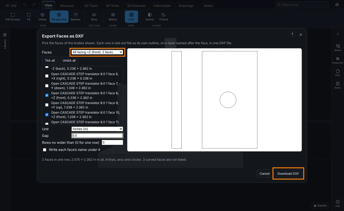
Options
- Faces: Pick faces in the list (you tick them yourself), or All facing +Z (front) and the like, one entry for each direction the flat faces point. The directions follow the viewer's own views: +Y is up, +Z is toward you in the Front view, +X is to the right. A face that is not square to an axis is listed as Slanted with its direction. Ticking or unticking a face by hand sets Faces back to Pick faces in the list.
- The face list: each face is named after its body and its number on that body, such as Plate face 3, then the way it points and its width and height in the unit picked. In one row the faces are laid out in the order you ticked them.
- Unit: Millimeters (mm), Centimeters (cm), Meters (m) or Inches (in). The file is written in that unit and says so, so your CAD or cutting program opens it at the right size. It starts on inches when your display unit is inches or feet, otherwise on your display unit.
- Gap: the space between two faces, in the unit picked. It starts at 10 mm (0.5 in, 1 cm or 0.01 m). 0 puts the faces edge to edge. At most 1 m (1000 mm).
- Rows no wider than (0 for one row): 0 lays every face in one row, left to right. A width lays the faces out in rows no wider than that, tallest faces first, each row above the last with the gap between rows. Every face must fit the width on its own. At most 100 m.
- Write each face's name under it: puts each face's name as text under its outline, on a layer of its own named FACE NAMES, so your cutting program can turn the names off. It starts unticked. The text is 3 mm high (0.125 in in inches).
What Is in the File
- One layer for each face, named after the face (Plate face 3). Two faces with the same name get _2, _3 and so on. Each layer has its own color.
- Each closed boundary of a face (the outside and every hole) is one closed outline: straight edges as lines, round edges as true arcs, a round hole as a circle. This is the same outline Export this face as DXF writes for one face.
- Each face is seen from outside the part, as if you looked straight at it.
- The file is DXF 2018 and says its unit, the source file and how the faces were laid out.
Limits
- Only flat faces are listed. Curved faces (a hole's wall, a round edge) are left out, and the window says how many.
- Bodies from a mesh file (STL, OBJ, 3MF) have no faces to pick. Use Export this face as DXF on a right click for one face of such a body.
- Faces are not turned or fitted into each other to save material: each face keeps its own direction and they are placed in rows.
- Bent sheet metal is not unfolded here. For a flat pattern use Export this face as DXF on a face of the bent part.
- A layer name holds at most 40 letters. Letters that DXF programs do not allow in a layer name (such as < > / : ; ? * | = and the comma) become _, and control, invisible or direction marks become spaces. A name written under a face is cut at 40 letters too, and the face gets room as wide as its name so names never run into the next face.
- At most 600,000 triangles read, 5,000 flat faces listed, 300 faces in one file, 200,000 boundary points of the picked faces, 100,000 lines, arcs and circles in one file, 500 points on one edge of a face, and 8 seconds to find the faces and again to fit the picked ones. Past any of these the window says so and nothing downloads.
- It needs the Advanced plan or higher, and on a shared model the Exports box ticked.
Common Mistakes and Messages
When something is wrong, the line under the picture says why in words and Download DXF is greyed out until it is put right.
- Download DXF is greyed out and the line says to tick the faces: it ends Tick the faces to export, or pick a direction. No face is ticked yet. Tick a face in the list, or pick a direction in Faces.
- "Gap is not a number. Type a plain number such as 10 or 0.5." or "Row width is not a number. Type a plain number such as 10 or 0.5." Type a plain number such as 10 or 0.5, with a point for decimals. Words, commas, minus signs and invisible characters (pasted from elsewhere) are not read.
- "Gap cannot be below 0. Type 0 or more." A minus sign was typed. Type 0 or more.
- "... wide, wider than the ... row. Type a wider row, or 0 for one row." One face is wider than the width in Rows no wider than. Type a wider row, or 0 for one row.
- "A gap of ... is more than the ..." Type a smaller gap.
- "The layout would be ..." The faces in one row are too long. Type a row width, a smaller gap, or untick some faces.
- "... faces are picked, more than the 300 one file can hold." Untick some faces and export the rest in a second file.
- "The picked faces have ... boundary points" or "The picked faces need more than 100,000 lines and arcs": untick some faces.
- "The outline of ... could not be fitted cleanly." That face's boundary is broken. Untick it and try again.
- "... has an edge of ... points, more than the 500 one outline can be fitted from." That face has a very finely meshed edge (often a spline). Untick it.
- "This part has ... triangles, more than the 600,000 this export can read." Hide some bodies and try again.
- "Finding the flat faces took longer than 8 seconds" or "Fitting the outlines took longer than 8 seconds": hide some bodies, or untick some faces, and try again.
- "The bodies shown came from a mesh file": a mesh has no faces to pick. Use Export this face as DXF on a right click.
- "None of the bodies shown has a flat face to export." Show a body with flat faces.
- "No body is shown." Show a body in the Model tree, then open the window again.
- "There is no solid yet, so there are no faces to export." A part drawn here has only sketches so far. Extrude something first.
- "This file is a 2D drawing already." A DXF, SVG or PDF is flat already.
- "Export faces as DXF on the Advanced plan or higher." The plan does not include exports.
- "The owner of this model has not allowed exports." The share does not have the Exports box ticked.
Tips
- To cut every plate of a weldment, pick the direction its plates face, untick the few you do not want, and set a row width the size of your sheet.
- Tick Write each face's name under it when the parts must be sorted after cutting, then turn off the FACE NAMES layer in your cutting program.
- Check the size the message gives against the part before you cut.