Drawing Notes, Balloons and Parts Table
Make Drawing can put notes, balloons and a parts table on the sheet. A note is your own words with a leader (a line ending in an arrow) to a part. A balloon is a numbered circle with a leader to a part; its number is that part's row in the parts table. The parts table lists each part with its item number, its name and how many there are. All of it goes into the DXF with the views.
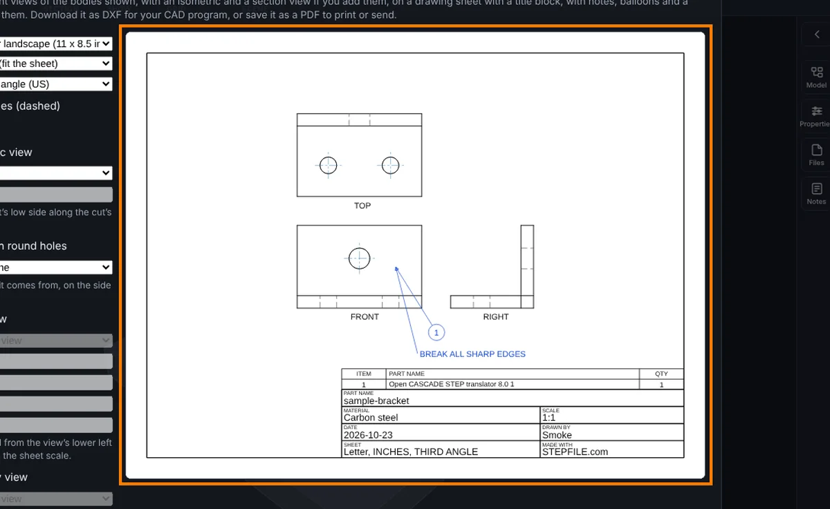
What you get: a parts table above the title block (ITEM, PART NAME, QTY), a numbered balloon pointing at each part and your notes with leaders, placed clear of the views and saved in the DXF with the rest of the sheet.
Step by Step
- Open a part or an assembly, and show the parts you want on the drawing. Only the parts shown are drawn and listed.
- Click the Drawings tab, then Make Drawing. Set the sheet, the scale and the views as usual (see Make Drawing). With more than one part shown, one click on Set up as an assembly drawing (under One sheet per part) does the rest of this at once: Tabloid (A3 on a metric display), the scale on Auto, the isometric view, the parts table, balloons on the isometric view, only the overall sizes, and hidden lines off. Change any of them afterwards. Locations of holes and slots belong on each part’s own sheet (One sheet per part), and the window says so if you ask for them on a sheet with several parts. The AI does the same with assembly true on drawing.make (anything else sent in the same call wins), and model_items_what picks all, overall or locate.
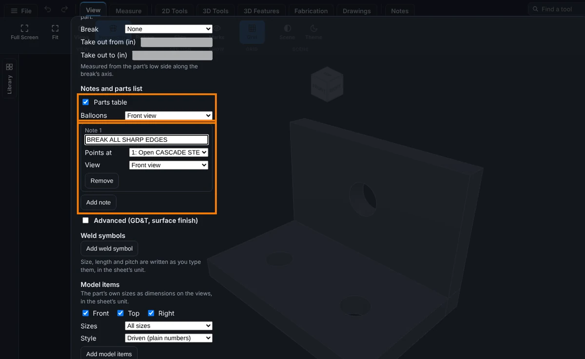
- At the bottom of the left side of the window, click Advanced options to open it, scroll to Notes and parts list, and tick or untick Parts table.
- Pick where the Balloons go: None, Front view, Top view, Right view or Isometric view.
- To add a note, click Add note. A box named Note 1 appears. Type its words, such as BREAK ALL SHARP EDGES, pick the part it points at in Points at and the view in View. Click Remove under a note to take it away.
- Check the preview. The line under it counts the table rows, the balloons and the notes. When something cannot be placed it says why and Download DXF is greyed out.
- Click Download DXF at the bottom of the window.
Options
- Parts table: a table above the title block, as wide as it, with the columns ITEM, PART NAME and QTY. When the parts have a material (the material the weight uses, set in the Model tree), a MATERIAL column is added before QTY. It starts unticked. The views move up to make room for it, so Auto may pick a smaller scale. With a parts table on the sheet Auto also tries the scales in between the ones in the Scale list (1:3, 2:3, 3:4 and so on) and takes the biggest that fits, and the line under the preview says which one it picked. When the views would be too small above the table, they may also use the whole height left of the table and the title block.
- Hardware: bought parts the model does not hold, one line each in the box under Balloons: how many, then what it is, such as 22 3/8-16 X 1 HEX BOLT, GR 5 or 22 3/8-16 HEX NUT. They are listed under the parts with the next ITEM numbers and need the parts table (up to 20 lines; the words are cut at 40 letters). They get no balloon. The AI asks for the same with hardware, parts_table and balloons in Make a drawing.
- Material and stock: when the table has materials, each row gives the material and its grade. The grade is the one set for that body: type it in the Grade box of the Model tree, or have the assistant set it with the body material command, and it is saved with the model. A body with no grade set shows A36 if it is carbon steel and nothing for other materials. A STOCK column gives the size of the block the part is cut from, from the part's own outside size: PL 0.25 X 3.1 X 3.5 for a plate (its thickness a quarter of the next size or less), BAR for anything thicker. The stock size has no allowance for cutting.
- Balloons: one balloon for each row of the parts table, on the view you pick, its number the row's ITEM number. It starts on None, so a drawing opens as it did before you used them. Balloons on the isometric view need Add an isometric view ticked. A balloon whose part is behind other parts in that view still gets its balloon: its leader ends in a small ring, in the middle of where the part would be, instead of an arrow, and the line under the preview says how many balloons do this. A note cannot do this; it needs a part you can see.
- Add note: adds a note at the end of the list. It is greyed out when there are 20 notes.
- Note words: plain text, at most 120 letters (an emoji counts as one). Emoji joined from several (a family, a flag with a sign, skin tones with a joiner) hold an invisible joiner and are refused like any hidden character. Long notes are broken into lines of at most 40 letters, at the spaces.
- Points at: the part the note's leader points at, by its item number and name. It starts on item 1.
- View: the view the note points into: Front view, Top view, Right view or Isometric view. It starts on Front view.
- Remove: takes that note away. The notes after it move up a number.
What a Part Is
- In a part with several bodies, each body shown is a part. Bodies with the same name, or the same shape, are one row, and QTY counts them (a left and a right gusset made the same are one row of 2).
- In an open assembly, each placed part is a part. The same saved model placed several times is one row, and QTY counts the placements.
- Rows are numbered 1, 2, 3 in the order the parts are shown in the Model tree. A part name is cut at 40 letters and ends in ...; a name with no letters is written Part and its number.
Where They Go
- A leader points at a place where the part can be seen in that view, as far inside it as it gets (on a ring, on the ring, not in its hole). A part too thin to show on the view's picture (a 1 mm gusset on a 2 m beam) is looked at again on its own, closer, so it still gets a point. When a part is hidden behind others in that view, the next placement of the same model is used; when none can be seen, the window says so.
- Each note and balloon is placed outside its view, on the line from the middle of the view through the point, turning 5 degrees at a time and then further out until it is clear of every view, the title block, the parts table and the other notes and balloons, inside the border.
- Layers: ANNOT (the notes, the balloons and their leaders) and BOM (the parts table). They are added to the file only when the sheet has them. A balloon is a circle in the DXF, its number centered in it.
Limits
- At most 20 notes on a sheet, 120 letters in a note and 60 rows in the parts table. The table also has to leave room for the views: it takes at most six tenths of the height above the title block (about 18 parts on A4, A3, Letter or Tabloid).
- Notes and balloons are placed for you. You cannot drag them yet; to move one, point it into another view, change the scale or pick a bigger sheet. A leader can cross a line of a view or another leader.
- One balloon for each row, on one view. The table has item, part name, material (when the parts have one) and quantity, with no part number or description yet, and one style.
- A note points at a part, not at an edge or a hole.
- Sizes are on the Model Items page. Weld symbols have a page of their own: Drawing Weld Symbols. Surface finish symbols and GD&T (geometric tolerance) frames have their own page: Drawing Surface Finish and GD&T Symbols.
- Finding where the leaders point takes at most 8 seconds and 60 million steps, and placing the notes and balloons at most 2 seconds. Past these the window says so.
Common Mistakes and Messages
- "Note 1 is empty. Type its words, or click Remove under it." A note was added and left empty, so Download DXF is greyed out. Type its words, or click Remove under it.
- "Note 1 is 121 letters long. A note holds at most 120; shorten it." A note holds at most 120 letters. Shorten it, or split it into two notes.
- "Note 1 has a hidden or control character in it" The words have an invisible character, often from text pasted from elsewhere (a direction mark, a zero width space, a soft hyphen or a line break). Delete the note's words and type them again.
- "There are 21 notes. A sheet holds at most 20" Remove some notes.
- "The balloons are set to go on the isometric view, which is not on the sheet." Tick Add an isometric view, or pick another view for the balloons. A note set to point into the isometric view says the same.
- "Balloon ... cannot be seen in the ... view (other parts cover it). Pick another view for the balloons." Pick another view for the balloons, or another view or part for the note.
- "Balloon ... finds no free place on the sheet clear of the views." Pick a smaller scale or a bigger sheet, or put the balloons on another view.
- "Note ... finds no free place on the sheet clear of the views." Shorten the note, pick a smaller scale or a bigger sheet, or point it into another view.
- "The parts table has ... rows, too many to leave room for the views" Pick a bigger sheet, or untick Parts table.
- "The parts table would have ... rows, more than the 60 one sheet can hold." Hide some parts, or untick Parts table and set Balloons to None.
- "Finding where the notes and balloons point took longer than 8 seconds" Hide some bodies, or open a simpler part, and try again.
Tips
- Put the balloons on the isometric view of an assembly: every part usually shows there.
- Use one short note for each instruction, such as BREAK ALL SHARP EDGES or WELD ALL AROUND, pointing at the part it is about.
- A general note for the whole drawing can point at the biggest part in the view with the most room around it.
Related Pages
- Make Drawing (Views, Sections and Center Marks)
- Make Drawing: Save as PDF and Projected View
- Drawing Weld Symbols
- Drawing Surface Finish and GD&T Symbols
- Bill of Materials
- Exporting Parts, Faces and Files
Weld symbols from the model: if the model has Weld Bead steps (3D Features, Weld Bead), Add the model’s welds in the Weld symbols section puts a fillet symbol on each bead, on the front, top or right view where the bead runs, sized from the bead’s leg, with its length and pitch for an intermittent bead and All around for an all-around bead. You can still change or remove each symbol. The AI does the same with welds_model true on drawing.make. The assembly set-up button, and the AI's assembly preset, also write part positions (Sizes: Overall sizes and part positions): the overall sizes, and each part's edges as locations from the view's corner. The button also writes the Weld note (ALL WELDS 1/4 FILLET UNLESS OTHERWISE NOTED, from the commonest size) when that box is empty, and the plain symbols of that size carry the tail TYP when there are two or more. A weld symbol's leader is kept inside its own view: it does not run across another view when there is a free place that avoids it. The bodies a Weld Bead step made are not drawn as parts: they are left out of the views, the parts table and the balloons, because the weld symbol says them (as a weldment cut list lists the members, not the welds). Weld sizes, lengths and pitches are written as shop fractions in inches (1/4, 1 9/16) or to two places, and whole millimeters.