Concentric Mate
Puts two round things on one shared center line. A pin in a hole, a bolt in a bore and a shaft in a bearing are all Concentric mates.
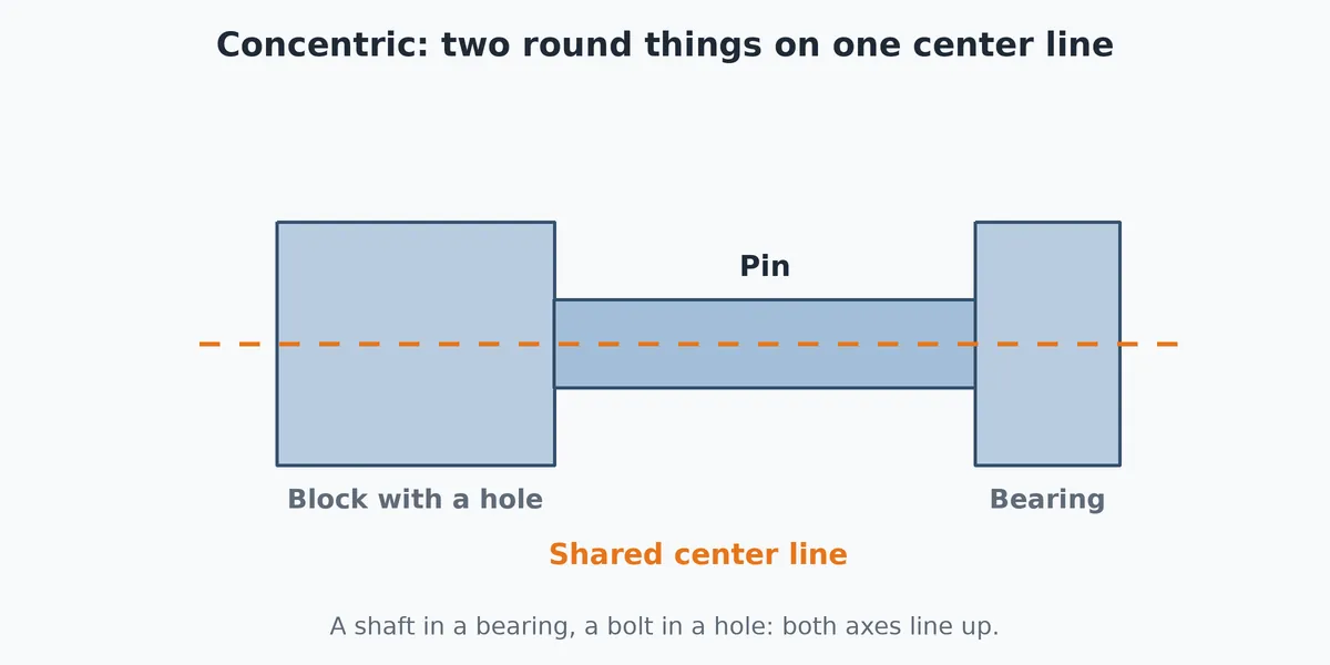
What you get: the two round picks share one center line (a pin in its hole), one mate named Concentric1 in the Mates folder; the pin can still slide along and turn about the line unless you add more.
When to Use It
- Drop a bolt into a hole
- Seat a shaft in a bearing
- Line up two round bosses
- Put a corner on the center line of a round hole
What It Does With Each Pair
The Concentric button is lit for these pairs of picks:
- Two round faces
- Two circular edges
- Round face with straight edge
- Round face with corner
- Circular edge with round face
- Circular edge with straight edge
- Two conical faces
- Conical face with round face
- Conical face with straight edge
- Circular edge with conical face
It lines up the two axes. Round faces, circular edges and conical faces all give an axis. When you pick two round things, Concentric is the first choice the window makes.
Step by Step
- Open an assembly (assemblies need the Pro plan) with at least two components in it. See Assemblies: Start and Insert Parts.
- Click Mate on the Assembly tab (or right-click a component and choose Assembly tools, Mate...). The Mate window opens on the Standard tab.
- Click the first entity on one component in the view. It appears in Mate Selections. You can also click the Front Plane, Top Plane, Right Plane or Origin row of a component or of the assembly in the Model tree.
- Click the second entity on a different component. After the second pick the parts move to show the result, and a small Quick Mate pop-up by the pointer lists the mates that fit. Leave it, or press Esc to close it; your two picks stay.
- Click Concentric in the Standard Mates list of the Mate window. Click the other buttons in the list to compare; only the mates that fit your two picks are lit. (A click on a button in the Quick Mate pop-up adds that mate straight away, as it stands, with no further steps.)
- If the pin should not spin, tick Lock rotation. If it points the wrong way, change Mate alignment.
- Click the green check (or press Enter) to add the mate. The message reads "Concentric1 added." and the window stays open for the next pair.
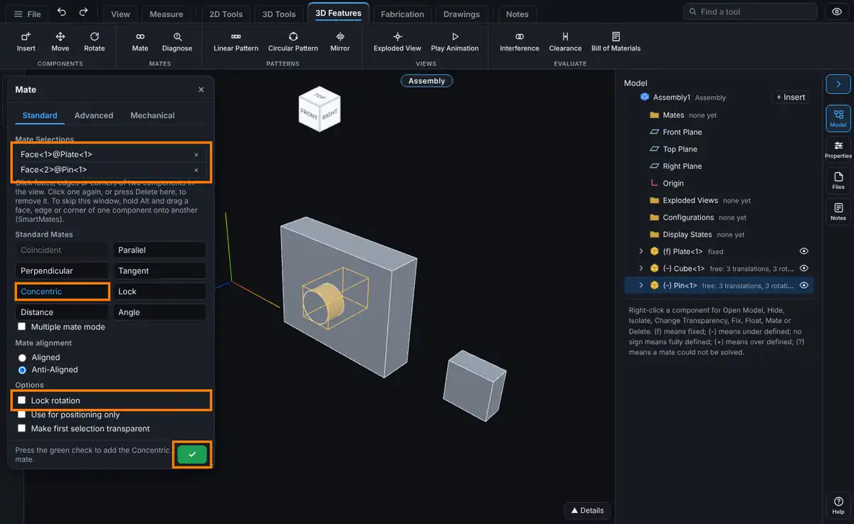
Options
- Mate alignment: Aligned points the two faces' normals (or the two axes) the same way. Anti-Aligned points them opposite ways. The choice shows only when both picks have a direction (a face, an edge or an axis), not when one is a corner. For two flat faces that touch face to face, Anti-Aligned is the usual one. The window picks the one closest to where the parts are now. You can also press Tab during a SmartMate drag, or right-click the mate in the tree and choose Flip Mate Alignment later.
- Lock rotation: keeps the part from turning about the shared axis, holding it in the turn it has when you add the mate.
- Use for positioning only: moves the parts as the mate would, but no mate is kept. The message reads "Positioned. No mate was added."
- Make first selection transparent: the component you picked first turns see-through so you can reach what is behind it.
- Multiple mate mode: the first pick is the Common reference, every further pick is a Component reference on its own component, and one mate is made for each. Create multi-mate folder groups them (MultiMate1, MultiMate2 and so on).
Tips and What to Expect
- Concentric leaves two freedoms: slide along the axis and turn about it. Add a Coincident mate on the faces to stop the slide. A hole-and-pin pair of picks is also made in one go by the SmartMate called Peg in hole (hold Alt, drag a circular edge onto another circular edge).
- If you want the turn but not the slide, use Hinge, which is a Concentric plus a Coincident in one step.
Common Mistakes and Messages
- The mate you want is grey. The two picks do not fit it. Remove one pick (click it again, or press Delete in Mate Selections) and pick a different entity.
- "Those entities have no mate in common." Every mate button is grey because no mate fits the two picks, for example two corners for Parallel. Remove one pick (click it again, or press Delete in Mate Selections) and pick a different face or edge.
- "Pick the second entity on a different component." Both picks were on the same component. A mate always joins two components, or a component and the assembly's own planes or origin.
- "Collapse the exploded view to add mates." Mates cannot be added while the assembly is exploded. Collapse it from its row in the Exploded Views folder. See Exploded Views.
- "This mate over defines the assembly. Force it to solve? Yes breaks the conflicting mate. No keeps it unsolved." The new mate fights the ones already there. Click No to keep it unsolved and look at it, then delete or change one of the two. See Mates: Fixing Mate Problems.
- Nothing moves. A fixed component does not move. Right-click it and choose Assembly tools, Float, or fix the other component's side on purpose.
- A bolt goes in from the wrong end. Switch Mate alignment to the other choice.