Up To Surface
An end condition for Extrude and Cut. Click a face, and the feature ends on it, as if that face reached out past its own edges. If you change the part so the face moves, the feature follows. This replaces the old Up to face button. For a guided example with pictures, see the Up To Surface Walkthrough.
What you get: an Extrude or Cut that ends exactly on the face you click (or a set distance short of it or past it), and follows that face when the part changes.
When to Use It
- Make a boss that ends exactly on a face, at any angle
- Cut a pocket up to a wall, a tilted face or a curved surface
- Stop a little short of a face to leave a gap, or run a little past it
- Tie a feature to a face, so it moves when that face moves
Which Faces Work
- Flat faces, at any angle to the sketch
- Cylindrical faces, such as a bore or a round post
- Spherical faces
- Conical faces, such as a countersink, a chamfer ring or a tapered post
- Toroidal faces, the round of a ring or a fillet turned about an axis
The face is treated as if it went on past its edges, so the feature can end on a surface that is wider than the face you clicked. A cone is carried on past its edges with the same apex, axis and angle, and a ring with the same radii. Any other kind of face is refused with this message: Up To Surface supports flat, cylindrical, conical, spherical and toroidal faces.
Step by Step
- Open a sketch on a plane or a face and draw a closed profile. Sketching is part of modeling, which comes with the Pro plans.
- Click Extrude (or Cut) on the Features tab.
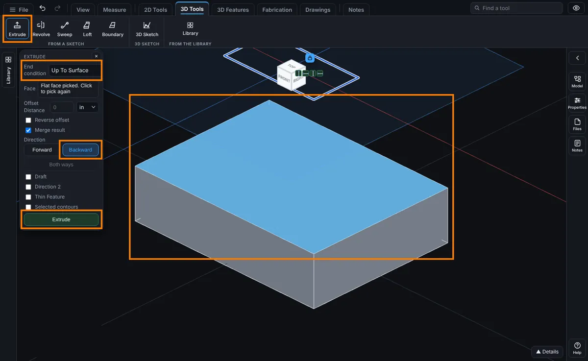
- In End condition, choose Up To Surface. A Face row, an Offset Distance box and a Reverse offset box appear.
- Choose a Direction toward the face. Both ways is off for this end condition.
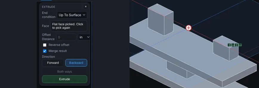
- Click the face on the part. It lights up in blue, and the message names what kind of face it is, for example "Flat face picked. Set an offset if you want one, then press Extrude."
- Type an Offset Distance if you want one. You can use any unit, like
1/8 inor3mm, or a formula (see Equations). The default is 0. - Click Extrude (or Cut). The feature ends on the face.
- The step reads up to surface in the Model tree, or offset from surface 1/8 in when it has an offset (see Offset From Surface).
Options
- End condition: Up To Surface. The other choices are Blind, Through All (Cut only) and Up To Next.
- Face: the face to end on. Click Pick face again to choose another.
- Offset Distance: how far from the face the feature ends. By default it stops short of the face by that distance. The End condition list also has Offset From Surface, the same with an Offset Distance it asks for and Translate surface (see Offset From Surface).
- Reverse offset: the offset goes the other way, so the feature runs past the face by that distance.
- Direction: Forward or Backward, toward the face.
- Merge result (Extrude only): join the new material to the bodies it touches, or keep it separate.
The Face Is Kept by Reference
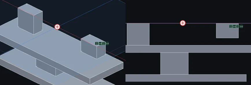
The step remembers the face, not a number. Every time the part is rebuilt, the face is found again. Make the plate under it thicker, and the feature ends on the new face. If the face cannot be found, the message says so: Up To Surface: the face it ends on is no longer on the part. An earlier step probably changed or removed it. Edit the step and pick the face again. Right-click the step, choose Edit Feature, click Pick face again and click the face.
Edit It Later
Right-click the step in the Model tree and choose Edit Feature. You can change the End condition, the Offset Distance, Reverse offset, Merge result, and click Pick face again. Press Esc or click the X to close the boxes without a change.
Tips and What to Expect
- A face parallel to the direction of the feature never meets it, and the message says so. A sketch that is already on the face has nothing to extend.
- An offset larger than the distance to the face is refused, because the end would fall behind the sketch.
- A Pattern can repeat an Up To Surface step. Every copy ends on the same face you picked, carried on past its edges, so a copy further along a sloped face is taller than the first. A copy that cannot reach the face is refused by its number, for example Copy 3 of 4 cannot be made. followed by the reason.
- An Offset Distance on a cone is measured square to the cone, and on a ring it makes the tube of the ring larger (stops short) or smaller (runs past).
- An older version of the viewer opens the step as a plain depth (the farthest distance measured here). When the end is flat, square to the direction and joins the part, the shape is the same. Otherwise it can differ, so open such models in this version.
- A viewer from 6.333.0 to 6.340.0 refuses a step that ends on a conical or toroidal face, and stops opening the model at that step. Open such models in this version.
Common Mistakes and Messages
- "That face is behind the sketch. Choose Backward." The face is on the other side of the sketch plane. Choose the other Direction (Backward), then press Extrude again.
- "The face cuts through the sketch." The face crosses the profile, so there is no single end. Pick a different face or move the sketch.
- "That face runs almost parallel to the extrude direction. Pick a different face." The face runs along the feature instead of across it. Pick a face that the feature runs into.
- "Up To Surface supports flat, cylindrical, conical, spherical and toroidal faces." The face you clicked is another kind, such as a free form face. Pick a flat or round face, or use Blind with a typed depth.
- "Up To Surface: the face it ends on is no longer on the part. An earlier step probably changed or removed it. Edit the step and pick the face again." Right-click the step, choose Edit Feature, click Pick face again and click the face.