Sheet Metal
Sheet Metal makes bent sheet parts the way a press brake shop thinks about them: a flat sheet of one thickness (the base flange), then flanges bent up from its straight edges (edge flanges), each bend with a true inside radius. Edges can also be folded back as a hem, stepped up with a jog, and corners can be rounded or chamfered with Break corner. A miter flange bends one flange along several edges at once, with the corners mitred, closed or cut back with a corner relief, so a tray or a box is one step. A sketched bend folds the sheet along a line you draw on it. The part keeps its thickness, bend radius, material and K-factor, and the finished part unfolds into a flat pattern with Export This Face as DXF.
What you get: a sheet metal part of one thickness with true inside bend radii, built one History step at a time (Base-Flange, Edge-Flange, Hem and the rest), and messages such as "Edge flange made." when each step is kept.
How to Start It
Click Sheet Metal on the Fabrication tab (or find it with Find a tool: sheet metal, bent part, flange, bend). Modeling must be open. The panel opens on Make a bent part: the sheet settings, the flat plate and its bends. That is all most parts need. The other tools, Base flange, Edge flange, Hem, Jog, Break corner, Miter flange and Sketched bend, are in the Advanced sheet metal box under it, shut until you open it; the box stays the way you left it. Edge flange, Hem, Jog and Break corner all work on the edge you pick with Pick an edge; Miter flange works on the edges you pick with its own Pick edges; Sketched bend works on one line drawn in an open sketch on the sheet.
The Sheet Settings
- Thickness: the sheet thickness, in any unit (2, 0.06 in, 16 gauge steel is 0.0598 in). From 0.05 mm up to 50 mm.
- Gauge: pick a sheet gauge and its thickness is typed into Thickness for you, in inches when your display is in inches or feet and in mm otherwise. The list follows the Material: sheet steel (Manufacturers' Standard Gauge, 3 to 30), stainless steel (7 to 30) or aluminum (Brown and Sharpe, 6 to 30). Each one shows its thickness in inches and mm, for example 16 ga, 0.0598 in (1.519 mm) for steel. When you type a thickness that is a gauge of the material (within half a thousandth of an inch), the list shows it; otherwise it says Type a thickness. Only the thickness is kept with the part.
- Bend radius: the inside radius of each bend, in any unit. Making it the same as the thickness is a common choice. It must be at least 0.01 mm and at most 100 times the thickness.
- Material: the row of the bend table the flat pattern takes its K-factor from (mild steel, aluminum or stainless steel). Mild steel is chosen first.
- K-factor (in Advanced sheet metal): where the bend keeps its length, from 0 (the inside of the bend) to 1 (the outside). Leave it empty to use the bend table for the material, which picks a K by the radius over the thickness.
These settings are kept on the steps the panel makes, so they are saved with the part. When you open the panel again, or open the part another day, it starts from them, and the flat pattern window starts from the part's own material and K-factor.
Make a Bent Part, Step by Step
- Click Sheet Metal on the Fabrication tab. Type the Thickness and the Bend radius, and choose the Material. The K-factor comes from the bend table for the material.
- Under Make a bent part, type the Width and the Length of the flat plate, in any unit. Width runs left to right in the Top view, Length up and down the screen.
- Under Bends, choose a side (Right, Left, Back or Front), type how far the flange reaches, measured from the outside corner of the bend as for an Edge flange, and the angle (90 is a square bend). Press Add a bend for another side, up to four sides; x takes a bend away.
- Press Make the bent part. The plate becomes a Base-Flange step in History and each bend an Edge-Flange step, so one Undo takes back one step. Bends on opposite sides each keep their own length and angle. Bends on sides that meet, such as Right and Back, are made as one Miter flange with the corner mitred, so they share one length and one angle.
- Press Flat pattern to lay the part out flat and write the DXF for the laser or the brake. A 100 by 50 plate, 2 thick, with a 2 radius, K 0.4 and one 25 long 90 degree bend on the right lays out 100 + 25 - 2 x (2 + 2) + 90 degrees x (2 + 0.4 x 2) = 121.40 long by 50.
The AI makes the same part with the sheet.make_bent_part command, for example bends "right 25 90; left 25 90", and lays it flat with sheet.flat_pattern.
For an outline that is not a rectangle, a plate on another plane or face, a hem, a jog or a broken corner, open Advanced sheet metal and use the steps below.
Base Flange, Step by Step
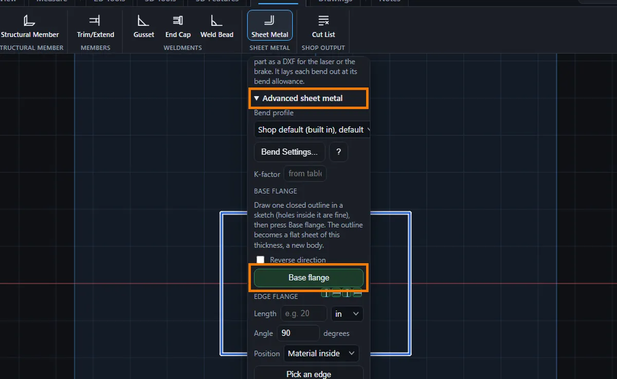
Open Advanced sheet metal first: Base flange, and every step below it, is in that box.
- Start a sketch on a plane or a flat face, and draw one closed outline: a rectangle, a polygon, an outline of lines and arcs or a circle. Outlines inside it become holes in the sheet. The outline can be up to 10 m across.
- Click Sheet Metal and type the Thickness and the Bend radius. Choose the Material, and type a K-factor only if you have your own.
- Tick Reverse direction if the sheet should be on the other side of the sketch.
- Press Base flange. The outline becomes a flat sheet of that thickness, as a new body, in one History step named Base-Flange.
Edge Flange, Step by Step
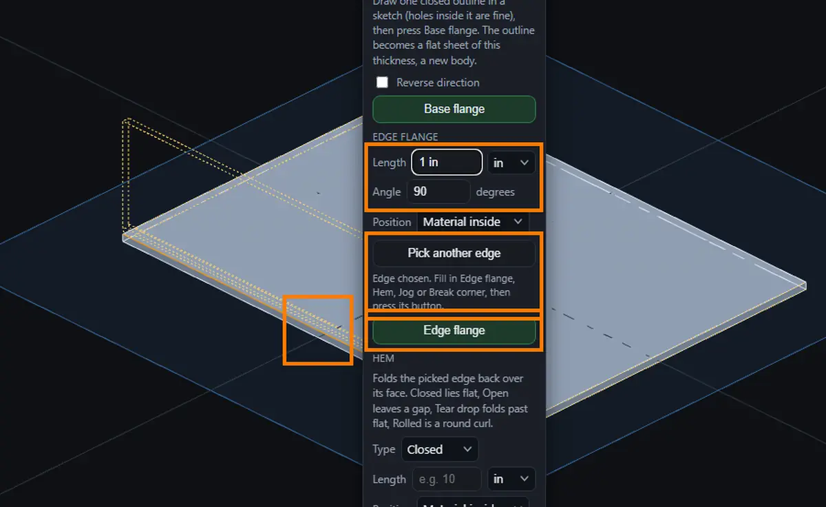
- With the Sheet Metal panel open, press Pick an edge. Every edge of the part is drawn in blue.
- Click a straight edge where the flat face of the sheet meets its square cut side. The flange rises on the side of the face you picked: pick the edge on the top face for a flange that goes up, or the matching edge on the bottom face for one that goes down. The chosen edge is drawn in orange.
- Type the Length: how far the flange reaches, measured from the outside corner of the bend (where the outside face of the sheet and the outside face of the flange would meet) to the end of the flange. With a 90 degree flange and Material inside, the part is exactly that tall over its outside face.
- Type the Angle: how far the flange is bent up, from 1 to 160 degrees. It starts at 90, a square flange.
- Choose the Position:
- Material inside (the default): the flange stays inside the old edge, so the part does not grow. The sheet is trimmed back by the bend before the flange.
- Material outside: the inside of the flange stands on the old edge, so the part grows by one thickness.
- Bend outside: the bend starts at the old edge and nothing is trimmed.
- Dashed lines show the flange before you keep it. Press Edge flange (or Enter in Length or Angle). The flange is one History step named Edge-Flange, and one Undo takes it away.
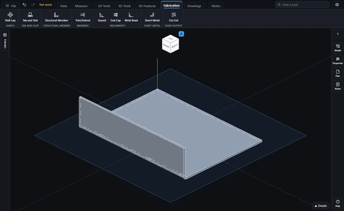
Each flange uses the Bend radius in the panel, and its thickness is always measured from the sheet at the edge you pick. To flange more edges, press Pick an edge again. A flange can go on an edge of another flange too.
Hem, Step by Step
A hem folds the edge of the sheet back over itself, for a safe smooth edge or a stiffer one.
- Press Pick an edge and click a straight edge of the sheet, just as for an edge flange. The hem folds back over the face you picked the edge on: pick the edge on the top face to fold it over the top.
- Choose the Type:
- Closed: folded flat onto the sheet. It keeps a hairline gap of 0.0008 in (0.02 mm) so the fold is a real bend that the flat pattern can unfold.
- Open: folded back flat with the Gap you type between the sheet and the hem.
- Tear drop: folded past flat, round the Gap, so the end leans back toward the sheet. Its Angle is from 181 to 260 degrees, 210 if you leave it empty.
- Rolled: a round curl with no straight part. Its Angle is from 181 to 260 degrees, 240 if you leave it empty.
- Type the Length (not for Rolled): how far the hem reaches back over the sheet, measured from the outside of the fold to the end of the hem.
- Type the Gap (not for Closed): the inside opening of the fold, which is twice its inside radius. It must be at least 0.0008 in (0.02 mm).
- Choose the Position:
- Material inside (the default): the outside of the fold is on the old edge, so the part does not grow. The sheet is trimmed back by half the gap plus the thickness.
- Material outside: the fold starts at the old edge, so the part grows by half the gap plus the thickness.
- Press Hem. It is one History step named Hem, and one Undo takes it away.
For example, an Open hem on a 2 thick sheet with a gap of 2 and a length of 15 rises to 6 over the bottom of the sheet (2 + 2 + 2), and its straight part is 15 - 3 = 12 long.
Jog, Step by Step
A jog steps the end of the sheet up (or down) by two opposite bends, like a joggle that lets one sheet lap over another.
- Press Pick an edge and click a straight edge of the sheet or of a flange. The jog rises toward the side of the face you picked the edge on: the top face to step up, the bottom face to step down.
- Type From edge: how far from the edge the first bend starts.
- Type the Offset: how far the end of the sheet is raised, face to face.
- Type the Angle of the two bends, from 1 to 90 degrees. It starts at 90, a square jog.
- The two bends use the Bend radius in the sheet settings at the top of the panel.
- Press Jog. The edge stays where it was (the jog does not make the part longer), and the step is named Jog in History.
The offset must be at least what the two bends rise by themselves: with 90 degree bends that is twice the bend radius plus the thickness. For example, with a 2 radius on a 2 thick sheet, an offset of 10 leaves a straight rise of 4 between the bends.
Break Corner, Step by Step
Break corner rounds or chamfers a corner of the sheet, right through its thickness.
- Press Pick an edge and click the short edge across the sheet at the corner (the edge as long as the sheet is thick).
- Choose the Kind: Round (a radius that meets both sides smoothly) or Chamfer (a straight cut the same distance back along each side).
- Type the Size: the corner radius, or the chamfer distance.
- Press Break corner. The step is named Break-Corner in History. Do it again for each corner.
Miter Flange, Step by Step
A miter flange is one flange bent along a run of edges that meet end to end, for example two sides of a bracket or all four sides of a tray. It is one History step, and the corners where the edges meet are made for you.
- Type the Length, the Angle and the Position in the Edge flange part of the panel. The miter flange uses them for every edge, with the Bend radius in the sheet settings.
- Under Miter flange, press Pick edges. Every edge of the part is drawn in blue.
- Click each edge the flange runs along, in any order: straight edges of the same flat face of the sheet (all on the top face, or all on the bottom face) that meet end to end. Each one turns orange. Click an edge again to take it off. Press Esc (or the button again) when you are done. Up to 32 edges.
- Choose the Corner, how the flanges meet where two edges meet:
- Miter (the default): both flanges are cut along the line that halves the corner, so they meet like a picture frame. The Gap keeps them apart, 0.0079 in (0.2 mm) if you leave it empty, from 0.0008 in (0.02 mm) to 0.3937 in (10 mm). Any outside corner from 30 to 179 degrees.
- Closed: the bends stop where the two inside bend lines cross, and the wall of one flange runs on over the end of the other, so the corner is closed but for the Gap. For square corners and 90 degree flanges.
- Round relief: both flanges stop short of the corner and a quarter circle is cut out of the sheet where the two inside bend lines cross, so the bends can fold without tearing. The Relief size is its radius.
- Square relief: the same with a square cut out. The Relief size is its side.
- Tear relief: both flanges stop where the two inside bend lines cross, and nothing is cut away. The sheet tears a little there when it is folded, which suits thin, soft sheet.
- Leave Relief empty to use the sheet thickness. Corner reliefs need square corners (90 degrees) and flanges of 90 degrees or less; past 90 degrees the two walls lean into each other at the corner, so use Miter there.
- Dashed lines show the flange before you keep it. Press Miter flange. It is one History step named Miter-Flange, and one Undo takes it away.
For example, on a 100 x 50 sheet 2 thick with a bend radius of 3, a miter flange 20 long at 90 degrees with Material inside on all four edges makes a tray that stays 100 x 50 and is 20 tall. With Round relief and an empty Relief size, each flange stops 7 short of each corner (5 for the bend and 2 for the relief).
Sketched Bend, Step by Step
A sketched bend folds a flat sheet along a straight line you draw on it, the way a press brake folds a blank on a marked line. The flat pattern stays the sheet you started from.
- Start a sketch on the flat face of the sheet (Sketch, then click the face), and draw one straight line with the Line tool where the sheet should fold. The bend runs right across the sheet along that line, however long you draw it, so the line only has to show where and which way. Construction lines do not count, so you can keep them.
- In the Sheet Metal panel, type the Bend radius (and the Material or K-factor) in the sheet settings at the top. The bend uses them.
- Under Sketched bend, type the Angle: how far the sheet folds, from 1 to 160 degrees. It starts at 90, a square bend. For a fold right back over the sheet use Hem.
- Choose the Position, where the bend sits against the line:
- Bend centerline (the default): the line is the middle of the bend.
- Material inside: the outside face of the folded side lies on the line.
- Material outside: the inside face of the folded side lies on the line.
- Bend outside: the bend starts at the line, on the side that folds.
- The side of the line with less of the sheet folds, toward the side of the face you drew on. Tick Flip direction to fold it the other way (down, if you drew on the top), and tick Fold the larger side to fold the other side of the line instead.
- Dashed lines show the bent sheet when you type in the section. Press Sketched bend (or Enter in Angle). It is one History step named Sketched-Bend, the line is used up as an outline is by an extrusion, and one Undo brings back both the flat sheet and the line.
For example, on a 100 x 50 sheet 2 thick with a bend radius of 3 and a K-factor of 0.4, a line across the sheet 70 from its left end and a 90 degree Bend centerline bend fold the last 30 up: the bend allowance is 5.97 (90 degrees times (3 + 0.4 x 2)), half of it each side of the line, so the part is 72.02 long and 32.02 tall. With Material inside the outside of the folded side stands on the line: the part is 70 long and 34.03 tall. Either way it lays out flat as the same 100 x 50 sheet.
Changing It Later
- Right-click the Base-Flange step in the History tree and choose Edit Feature to retype its depth: the depth is the sheet thickness, and every flange rebuilds at the new thickness.
- Edit Feature on an Edge-Flange step retypes its length, angle, radius and position, and the part rebuilds.
- Edit Feature on a Hem step retypes its type, length, gap, angle and position; on a Jog step its distance from the edge, offset, angle and radius; on a Break-Corner step its kind and size; on a Miter-Flange step its length, angle, radius, position, corner, gap and relief size (the edges stay the ones you picked); on a Sketched-Bend step its angle, radius, K-factor (empty uses the bend table of its material), position and Flip direction, and Fold the other side folds the other side of the line (the line stays the one you drew).
The Flat Pattern
Right-click a flat face of the finished part and choose Export, Export This Face as DXF, then Whole flat pattern (unfolded). Each bend lays out flat at its bend allowance, the angle times (inside radius + K x thickness), so a 100 long sheet with one 90 degree flange 20 long, 2 thick with a 3 radius, Material inside and K 0.4, lays out 95 + 5.97 + 15 = 115.97 long. Hems (up to 260 degrees) and jogs unfold the same way: the Open hem above, with K 0.4, lays out 97 + 5.65 + 12 = 114.65 long, and the jog above (from edge 20) lays out 80 + 2 x 4.40 + 4 + 14 = 106.80 long. Broken corners show in the outline. A miter flange unfolds too: the tray above, with Miter corners and K 0.4, lays out 131.94 x 81.94 (90 + 2 x (5.97 + 15) by 40 + 2 x (5.97 + 15)), with a notch at each corner where the mitred bends were. Closed corners and corner reliefs lay out flat the same way, the longer wall of a Closed corner as a wider flap. A sketched bend lays out as the sheet you drew, as long as the flat pattern uses the same K-factor the bend did: the panel's K-factor, or the bend table of the panel's material. See Export This Face as DXF.
What Is Refused, and What to Do
Each of these says so in plain words and leaves the part as it was:
- Base flange with no sketch open, no closed outline, or more than one separate outline: draw one closed outline and try again.
- An edge that is curved, or where a face is curved (a bend or a round): pick a straight edge of a flat part of the sheet.
- An edge where the two faces do not meet square, or a corner edge shorter than the sheet is thick: pick a long edge of the flat face.
- A side face with a notch, a hole or a step along the edge: a flange needs a plain straight edge.
- A flange too short for its bend: the length is measured from the outside corner, so it must be more than the bend takes up. Type a longer length or a smaller radius.
- Not enough plain sheet behind the edge for the trim (a hole, a cut-out or another flange is in the way): try Bend outside, a smaller radius, or another edge.
- An edge next to a flange you already made, for example the second side of a box: once an edge is flanged, the cut side of each edge beside it is no longer a plain strip, so it is refused with the message about a notch, a hole or a step. Flange edges that do not meet at a corner, such as two opposite edges, or use Miter flange for edges that meet at a corner.
- A hem that is too short for its fold, a tear drop hem whose end would touch the sheet (it says the longest length that fits), or a gap under 0.0008 in (0.02 mm) (choose Closed instead).
- A hem that would reach back past the far side of the sheet: it says the longest length that fits.
- A jog offset smaller than its two bends rise by themselves, or a jog that starts too near the edge for its bends to fit: it says the smallest offset or distance that works.
- Break corner on an edge longer than 1.9685 in (50 mm), a curved or already rounded corner, a corner that turns inward, or an edge where the sheet carries on past its ends: pick the short edge across the sheet at an outside corner.
- A corner round or chamfer bigger than its sides, or one that runs into a hole or another broken corner: use a smaller size.
- Miter flange with fewer than two edges, edges that do not meet end to end in one run, the same edge twice, edges on two faces or two bodies, more than two edges at one corner, or a corner that turns inward or is sharper than 30 degrees: pick edges of one face that follow on from each other round its outside.
- A Closed corner on a flange that is not 90 degrees, a corner relief on flanges past 90 degrees, or a Closed corner or a corner relief on a corner that is not square: use Miter there.
- An edge too short for its corners (the flanges at its two ends would meet), a relief bigger than the sheet at the corner, or a relief that runs into a hole: use shorter edges, a shorter flange, a smaller radius, gap or relief.
- Sketched bend with no sketch open, no line, more than one piece in the sketch, or an arc or a run of lines: draw one straight line on the sheet and try again.
- A bend line that is not on a flat face of the sheet, misses the sheet, crosses two bodies, or has sheet on one side only: draw it in a sketch on the face, across the sheet.
- A bend line that crosses a hole, a slot, a flange or another bend, or a bend whose strip (as wide as the bend allowance) is not plain sheet with edges square to the line: move the line to plain flat sheet.
- A bend that reaches past the edge of the sheet: move the line further in, use a smaller radius, or fold the other side.
- A flange, hem, jog, miter flange or sketched bend that runs into other material, for example a block standing on the sheet where the flange goes: move the block, or pick another edge.
- A flange whose edge moved when you changed an earlier step, where it can no longer tell which edge you meant: delete the flange and make it again on the edge you want.
- A thickness under 0.05 mm or over 50 mm, an outline over 10 m across, or a length, angle or radius that is empty, zero, not a number or too big.
Common Mistakes and Messages
- "Open a sketch and draw the outline of the sheet first (Sketch, then a face or a plane). Then press Base flange." Base flange needs an open sketch with one closed outline.
- "A base flange is one sheet, and this sketch has 2 separate closed outlines. Keep one outline (holes inside it are fine) and press Base flange again." Delete the extra outline.
- Edge flange stays grey. No edge is chosen yet. Press Pick an edge, then click a straight edge of the sheet, and Edge flange turns on.
- "is too short for its bend: its length is measured from the outside corner, so it must be more than the bend radius plus the thickness" The message names the side and ends with the least length in mm. In Make a bent part, type a longer flange or a smaller radius.
- "Bends on sides that meet are made as one miter flange, so they share one length and one angle." Give Right and Back (or any two sides that meet) the same length and angle, or bend opposite sides only.
- "A sketch with pieces is open. Close or clear it first, or use Base flange under Advanced sheet metal to bend that outline." Make a bent part draws its own plate on the Top plane.
- "Type the flange length, measured from the outside corner of the bend." The Length box is empty.
- "Type a flange angle from 1 to 160 degrees (90 is a square flange)." For a fold right back over the sheet use Hem.
Tips
- A channel or a U shape works well: flange two opposite edges of the base flange. A box or a tray with flanges on all four sides cannot be made with Edge flange, because the edges beside a flange are refused. Pick all four edges for one Miter flange instead.
- When you retype the thickness of the base flange, each flange follows its own edge: a flange on the top edge stays on the top. In the same way a sketched bend follows the face its line was drawn on, and folds the same side of the line.
- A K-factor from your own press brake tests is the most accurate. Type it once in the panel and the part keeps it.
- If your press brake chart gives a bend allowance or a bend deduction rather than a K-factor, choose it under Method in the flat pattern window of Export This Face as DXF and type it there.
- A gauge is a nominal size. Galvanized steel runs a little thicker than plain sheet steel of the same gauge, and a mill's sheet can be a few thousandths off: measure the sheet and type its thickness when it matters.
Limits for Now
- Make a bent part makes a rectangular plate on the Top plane with one bend per side, up to four, and sides that meet share one length and angle. Other outlines, other planes and faces, and hems, jogs and the rest are under Advanced sheet metal.
- Edge flange does one straight edge per flange, and no flange on an edge that meets another flange at a corner; Miter flange does several edges with mitred, closed or relieved corners where they meet. Flanges along curved edges and sketched flange profiles are not made yet.
- A miter flange has one length, angle and corner for all its edges, runs round outside corners of one flat face only, and puts no relief where the run of edges ends. Where an open run ends against a side that is not square to it, use Bend outside: Material inside and Material outside are refused there. Closed corners and corner reliefs are made on square corners only; a Closed corner needs 90 degree flanges, and a corner relief flanges of 90 degrees or less.
- A hem or a jog runs the full length of one straight edge. A jog line drawn in a sketch, a jog across a bend, rolled and tear drop hems past 260 degrees, and hem corners that are mitred or relieved are not made yet.
- The panel breaks one corner per step, and Break corner adds no relief cut-outs.
- A flange runs the full length of the edge.
- A sketched bend takes one straight line per step, right across one sheet. The line must cross plain flat sheet: not a hole, a slot, a flange or another bend, and where the sheet bends its edges must run square across the line. A curved bend line and several lines in one step are not done yet. To lay a bend flat again and cut on it, see Sheet Metal Unfold and Fold.
- A sketched bend keeps the flat pattern with the K-factor it was made with. If you later change the material or K-factor for the flat pattern, the flat pattern of the bent part grows or shrinks by the difference in bend allowance.
- A view only share cannot make or change sheet metal steps.
- The gauge lists are sheet steel, stainless steel and aluminum only. There is no galvanized, copper or brass list yet: type the thickness.
- A typed bend allowance or bend deduction is one value for every bend of the part, for a 90 degree bend at one inside radius. A part with bends of different radii, or a chart with a value for each angle, needs the K-factor for now.
Bend Profiles
The gauges and Unfold use the press brake profile chosen in the Bend profile list in Advanced sheet metal. Choose Shop default for the StepFile bend table, or a profile of your own; see Bend Settings and Machine Profiles.