Hole
Hole drills holes sized for a screw or a pipe thread. You choose the kind (plain, counterbore, countersink or tapped, and for the first three a straight slot instead of a round hole), the screw or pipe thread it is for and how it ends. Then you click on a sketch where each hole goes and apply them all as one step.
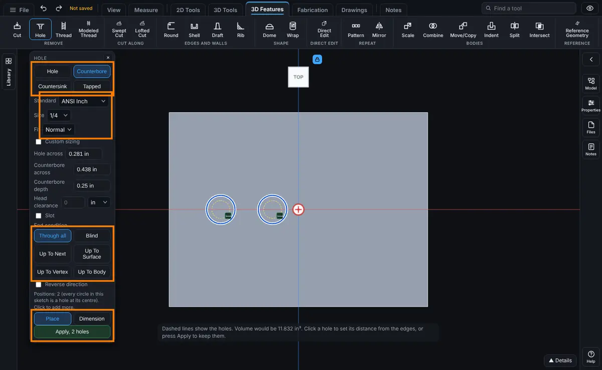
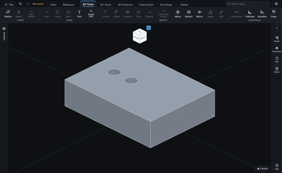
What you get: holes of the right size for your screw or pipe thread, at the places you clicked, made as one step in the Model tree, and a message such as 2 holes made: counterbore for 1/4, 0.281 in across, 2 places, through all.
When to Use It
- Drill bolt holes for a standard screw size with the right clearance
- Make a counterbore so a socket head screw sits below the surface
- Make a countersink for a flat head screw
- Make a tapped hole and record its thread, with a note, and cut the real thread if you need it
- Make a pipe tap hole for an NPT or BSPP fitting
- Make slots, so a part can slide a little before its screws are tightened
- Place a whole pattern of holes at exact distances from the edges
Step by Step
- Open a sketch on a flat face of the part or on a plane (see Planes and Faces). Holes go on a sketch.
- Click Hole on the Features tab. The panel is split into the kind of hole and the positions.
- Choose the kind: Hole, Counterbore, Countersink or Tapped. For a slot, tick Slot and type the Slot length and Slot angle (see Slot Holes below).
- Choose the Standard (ANSI Inch, ANSI Metric, ISO, DIN, JIS, BSPP pipe (G) or NPT pipe) and the Size, the screw or pipe thread the hole is for. Choose the Fit (not for Tapped): Close, Normal or Loose (ISO and DIN call these Fine, Medium and Coarse; JIS calls them Grade 1, Grade 2 and Grade 3). The sizes fill in from these choices.
- Choose the End condition: Through all, Blind, Up To Next, Up To Surface, Up To Vertex or Up To Body. For Blind type the Depth. For Up To Surface click the face the holes end on. For Up To Vertex click near the corner the holes end level with, and for Up To Body click the body they run up to.
- Place is on when the panel opens (click it again after using Dimension). Click on the sketch where each hole goes. Each click drops a hole there. Every circle in the sketch (not a construction circle) counts as a hole position.
- To set a distance from an edge, click a placed hole and read its distances to the part's edges, or click Dimension, click a hole, then an edge or another hole, and type the distance (see Smart Dimension).
- Watch the dashed preview. Click Apply. The button reads Apply, 3 holes when three are placed.
Options
- Hole, Counterbore, Countersink, Tapped: the kind of hole.
- Standard and Size: ANSI Inch sizes run from #2 to 1 in and ANSI Metric from M2 to M20. ISO and DIN run from M1.6 to M36, JIS from M2 to M24, BSPP pipe from G1/8 to G2, and NPT pipe from 1/16 to 2. The panel starts on ANSI Inch or ANSI Metric, whichever matches your display unit. A standard lists only the hole kinds and sizes included here for it. A kind not included is greyed out, and resting the pointer on it says which standard to choose instead. The size list for a kind shows only the sizes that standard gives for it.
- Fit (not Tapped): how much clearance there is around the screw.
- Custom sizing: tick it to type every size box yourself instead of using the looked-up values. Boxes take any unit.
- Counterbore across and Counterbore depth (Counterbore): the wider part and how deep it goes from the surface.
- Head clearance (Counterbore): extra depth so the screw head sits below the surface.
- Countersink across and Countersink angle (Countersink): the width at the surface and the included angle. It is 82 degrees for the inch standard and 90 for metric.
- Tapped: the hole is drilled at the tap drill and the thread, such as
1/4-20 UNCorM6x1.0, is recorded with the step. The panel shows the thread, and the Tap drill box shows the drill the standard's table gives. The thread is a cosmetic mark. It does not change the geometry (see Cosmetic Thread), unless you tick Modeled thread. See Tapped Holes below. - Thread series (Tapped, ANSI Inch): Coarse (UNC), the usual thread, or Fine (UNF), which has more threads per inch and its own tap drill.
- Thread note (Tapped): optional words kept with the hole, like
use thread locker. They show in the Model tree, in the thread callout and in Properties. - Modeled thread (Tapped): ticked, a real helical thread is cut in every hole as well. Hand chooses Right hand (the usual) or Left hand.
- Slot (Hole, Counterbore and Countersink): ticked, each hole is a straight slot centred where you click, as wide as the hole across. Greyed out for Tapped.
- Slot length (Slot): from the centre of one round end to the centre of the other. The slot is this plus one width long overall.
- Slot angle (Slot): how far the slot is turned from the sketch's right, counter clockwise as you see it, in degrees. 0 runs left to right and 90 runs up the screen.
- End condition: Through all, Blind with a Depth (how deep the full diameter goes), Up To Next, Up To Surface, Up To Vertex or Up To Body (see below). A blind hole also has Drill point, 118 degrees: ticked gives a pointed bottom, unticked a flat bottom. A blind tapped hole also has a Thread depth, starting at twice the screw size.
- Reverse direction: holes run into the part from the face they are on. Tick this when holes placed on a plane point the wrong way.
- Place and Dimension: drop holes, or set their distances.
Slot Holes
- Choose Hole, Counterbore or Countersink, the standard, the size and the fit as for a round hole.
- Tick Slot. Type the Slot length, centre to centre, in any unit (like 1 in or 25 mm), and the Slot angle.
- Place the slots on the sketch as you would place holes: each click is the middle of a slot.
- Watch the dashed preview, then click Apply. All the slots are one step in the Model tree, named like Counterbore slot for 1/4, 0.281 in wide, 1 in long, 2 places, through all.
The slot is the hole's own shape carried along a straight line: a counterbore or countersink runs round the whole slot at its own depth, and a blind slot with Drill point ticked has a pointed groove along its bottom (untick it for a flat bottomed slot, as a milling cutter leaves). Through all, Blind and Reverse direction work as for a round hole.
Worked example: a plain slot 0.25 in wide and 1 in long through a 0.5 in plate removes (3.1416 x 0.125 x 0.125 + 0.25 x 1) x 0.5 = 0.1495 cubic in (2450.6 cubic mm). In millimetres, a 6 mm wide, 25 mm long slot 12 mm deep with a flat bottom removes (3.1416 x 3 x 3 + 6 x 25) x 12 = 2139.3 cubic mm.
What slots do not do yet: a slot cannot be tapped, cannot end Up To Next, Up To Surface, Up To Vertex or Up To Body, and cannot be repeated by a pattern at sketch points or a fill pattern (In a row, Round an axis and Mirror work). Edit Feature changes the sizes, the end condition, the Slot length and the Slot angle of a slot step; a slot cannot be switched to Tapped, Up To Next, Up To Surface, Up To Vertex or Up To Body there (it says so in words). Only straight slots are offered; for a curved slot, draw an Arc Slot in a sketch and cut it.
Tapped Holes
- Choose Tapped, then the Standard (ANSI Inch, ANSI Metric, ISO, DIN, JIS, BSPP pipe (G) or NPT pipe) and the Size. For ANSI Inch choose the Thread series too: Coarse (UNC) or Fine (UNF).
- Read the thread under the size, like
Thread 1/4-28 UNF, and the tap drill in the Tap drill box: 0.213 in for 1/4-28 UNF, 0.201 in for 1/4-20 UNC, 5 mm for M6. To drill another size, tick Custom sizing and type it. - Choose the end condition. Blind has a Depth for the drill and a Thread depth for the thread (at most the drill depth). Through all, Up To Next, Up To Surface, Up To Vertex and Up To Body run the thread the whole length of the hole.
- Type a Thread note if you want one. It is kept with the hole and shown with its thread, like
M6x1.0 - 6H, 12 mm deep (use thread locker). - Tick Modeled thread to cut the real thread too, and choose the Hand. The line under it says the pitch and how deep the groove is.
- Place the holes and click Apply. The holes, their cosmetic thread, the note and any modeled thread are ONE step in the Model tree, named like Tapped M6x1.0, 5 mm drill, 2 places, thread 12 mm deep, drill 15 mm deep, modeled thread, note: use thread locker. One Undo takes it all away, and Redo puts it all back.
The modeled thread is cut the way Modeled Thread cuts one: a 60 degree V groove of the thread's pitch, starting at the rim of each hole, as deep as half the major diameter less the tap drill (0.5 mm for M6 in a 5 mm hole, 0.0245 in (0.622 mm) for 1/4-20 UNC). Worked example: two M6 holes 15 mm deep with a 12 mm thread in a block remove the two drilled holes plus the two grooves; each groove is a little under 2 x 3.1416 x 12 x 0.5 x 0.5 x 0.5774 x (2.5 + 0.5 / 3) = 29.0 cubic mm, because the first turn runs out at the rim.
What tapped holes do not do yet:
- A modeled thread is at most 50 turns in a hole and at most 20 holes in one step. A through hole longer than 50 turns is refused: choose Blind with a shorter Thread depth, or leave Modeled thread unticked.
- The modeled threads of one step must be cut within 60 seconds when you make or edit it (10 minutes when a saved part is opened or rebuilt unchanged), or the step is stopped and the part left as it was.
- NPT is a tapered thread and is not modeled; its Modeled thread box is greyed out, and a tick left from another standard is set aside (NPT holes are drilled and their thread recorded). The cosmetic thread records it.
- The dashed preview shows the drilled holes only; the thread is cut when you click Apply.
- A Pattern or Mirror cannot copy a tapped hole's modeled thread yet: it is refused in words, not dropped. Place every hole in the one Hole step, or untick Modeled thread on the step first.
- A Thread note is at most 60 letters (an emoji counts as one; spaces at either end are not counted). Direction marks, zero width spaces, line breaks and other hidden characters are refused.
- Edit Feature changes the note, Modeled thread and the Hand of a tapped hole; the Thread series and the size stay as made.
- UNF is offered for ANSI Inch only. Metric fine threads are not included yet: tick Custom sizing for another drill, or use Modeled Thread on the hole afterwards for another pitch.
Pipe Tap Holes
A pipe tap hole is a Tapped hole with a pipe standard: choose NPT pipe or BSPP pipe (G) as the Standard, then the pipe size. The hole is drilled at the tap drill and the pipe thread is recorded as a cosmetic thread, exactly like any tapped hole.
- NPT pipe (American taper pipe thread): sizes 1/16 to 2. A 1/4 NPT hole is drilled at 7/16 in (0.4375 in) and its thread note reads like
1/4-18 NPT, 0.402 in deep. A blind NPT thread starts at the effective thread length (L2) of ASME B1.20.1, the length of a tight joint: 0.402 in for 1/4, 0.534 in for 1/2. - BSPP pipe (G) (parallel pipe thread): see Where the Sizes Come From.
- NPT is a tapered thread. The hole here is the straight tap drill used when the thread is tapped without a taper reamer, and the taper is in the thread note only, as CAD programs draw a pipe tap's cosmetic thread. The cosmetic thread does not change the volume or the weight.
Up To Next and Up To Surface
- Up To Next: each hole runs through the material it starts in and stops where it comes out, at the first face it meets on the way out. A hole on top of a plate that stands above another plate goes through the top plate only.
- Up To Surface: click the face the holes end on (the Face row of the panel). Each hole runs to that face, carried on past its own edge, through any gap and any part in between. Flat, cylindrical, conical, spherical and toroidal faces work. The face is found again every time the model rebuilds, so the holes follow when an earlier change moves it.
- Every hole finds its own end, so holes over a step in the part stop at different depths. The end follows the face exactly, even a slanted one, and the bottom is a flat bottom (no drill point). A counterbore or countersink keeps its own depth at the top, and a tapped hole's thread runs the whole length of the hole.
- One step can place at most 100 places with these two end conditions, because each hole is worked out on its own. Holes that take more than 30 seconds to work out are refused and nothing is changed: place fewer holes in one step. The dashed preview is drawn for at most 12 such holes, and only when it is quick; press Apply to make more.
- A Pattern cannot repeat a hole that ends Up To Next or Up To Surface yet: A pattern cannot repeat a hole that ends Up To Next or Up To Surface yet. Place every hole in the one Hole step, or use Blind or Through all. A Mirror cannot copy one either: A mirror cannot copy a step that ends Up To Next or Up To Surface yet.
- A viewer older than this version cannot open a hole step with these end conditions and stops at that step. Open such models in this version.
Up To Vertex and Up To Body
- Up To Vertex: click near a corner of the part (the Corner row of the panel). Every hole ends on the flat plane through that corner, square to the hole, so all the holes of the step are the same depth: the distance from the sketch to the corner along the way the holes run. Use it to stop holes level with a step or a ledge without typing a depth. The corner is found again every time the model rebuilds: when an earlier change makes the plate under it thicker, the holes follow the corner.
- Up To Body: click a body (the Body row of the panel). Each hole runs through whatever is in its way, other bodies and gaps alike, until it meets that body, and stops at the first face of it the hole reaches. It never cuts into that body. Use it on a part made of several bodies, to drill through some plates and stop on another. The body is found again every time the model rebuilds.
- As with Up To Next, the bottom is a flat bottom (no drill point), a counterbore or countersink keeps its own depth at the top (the hole must run deeper than the head), a tapped hole's thread runs the whole of the hole in the part it starts in, and one step can place at most 100 places, with the same 30 second limit and a dashed preview for at most 12 such holes.
- Worked example, Up To Vertex: a hole 0.25 in across started on top of a block 1.5 in tall, ending level with a corner 1 in below the top, removes 3.1416 x 0.125 x 0.125 x 1 = 0.0491 cubic in (804.4 cubic mm). In millimetres, a 10 mm hole ending level with a corner 20 mm down removes 3.1416 x 5 x 5 x 20 = 1570.8 cubic mm.
- Worked example, Up To Body: three plates 10 mm thick stand 20 mm apart. A 10 mm hole from the top of the top plate, Up To Body with the bottom plate picked, goes through the top and middle plates and stops on the bottom one: 3.1416 x 5 x 5 x 20 = 1570.8 cubic mm. Up To Next would stop after the top plate (785.4 cubic mm) and Through all would go through all three (2356.2 cubic mm).
- A Pattern cannot repeat a hole that ends Up To Vertex or Up To Body yet: A pattern cannot repeat a hole that ends Up To Vertex or Up To Body yet. Place every hole in the one Hole step, or use Blind or Through all. A Mirror cannot copy one either: A mirror cannot copy a step that ends Up To Vertex or Up To Body yet.
- A slot cannot end Up To Vertex or Up To Body yet, and a viewer older than this version cannot open a hole step with these end conditions.
Where the Sizes Come From
Every size in the ISO, DIN, JIS and BSPP lists is copied from the published standard. Nothing is worked out or guessed. A size we could not check against the published standard is left out.
- ISO: clearance holes from ISO 273 (Table 1, fine, medium and coarse series). Countersinks from ISO 15065 (Table 1, the smallest countersink diameter, 90 degrees, for screws with ISO 7721 heads), M1.6 to M10. Tap drills from ISO 2306 (Table 7, coarse threads). ISO publishes no counterbore sizes, so Counterbore is greyed out.
- DIN: clearance holes from DIN EN 20273, which is ISO 273 word for word. Countersinks from DIN 74 type F (Table 3, 90 degrees, for socket countersunk screws to ISO 10642, which replaced DIN 7991), M3 to M20. Tap drills for coarse threads from DIN 336, the same numbers as ISO 2306 Table 7 (5 mm for M6, 8.5 mm for M10), M1.6 to M36. No counterbore sizes are built in for DIN yet: choose ANSI Metric for a counterbore.
- JIS: clearance holes from JIS B 1001, grades 1, 2 and 3. Tap drills for coarse threads from JIS B 1004, the size less one pitch as ISO 2306 prints them (5 mm for M6), M2 to M24. The counterbore sizes JIS B 1001 also gives are not included here yet.
- BSPP pipe (G): tapped holes only, for parallel pipe threads (ISO 228). The tap drill comes from ISO 2306 (Table 5), for example 11.8 mm for G1/4. The thread note reads like
G1/4, through, with no class letter, because this pipe thread has one class. A blind pipe thread starts one major diameter deep. - NPT pipe: tapped holes only, for American taper pipe threads. The tap drills are the common shop chart for tapping without a taper reamer (for example 11/32 in for 1/8, 7/16 in for 1/4, 23/32 in for 1/2). The major diameter is the pipe's outside diameter from ASME B36.10 (0.540 in for 1/4) and the default thread depth is L2 from ASME B1.20.1. The thread note has no class letter.
- ANSI Inch and ANSI Metric are as before: inch clearance holes from ASME B18.2.8, metric from ISO 273, with counterbores for socket head cap screws and countersinks for flat head screws. Inch tap drills are the usual 75 percent thread drills: for UNC as before, and for UNF from the common tap drill chart (#50 for 2-64, #3 for 1/4-28, Q for 3/8-24, 59/64 in for 1-12).
The standard is saved with the step. A hole made earlier keeps the sizes it was made with, so opening an old part never changes its holes.
Edit It Later
Right-click the step in the Model tree and choose Edit Feature. You can change the kind, every size and the end condition in place. A slot step also shows Slot length and Slot angle, degrees; a new angle turns each slot about its own centre. For Up To Surface the face is kept; click Pick face again to choose another. For Up To Vertex and Up To Body the corner or body is kept the same way (the Ends at button reads Corner kept or the body's name); click it to pick again. The positions stay. To move a hole, delete the step (Undo brings the positions back into the sketch) and place it again.
Tips and What to Expect
- A hole for a 1/4 in screw with a Normal fit is 0.281 in across. With a Close fit it is 0.266 in and with a Loose fit 0.312 in.
- A tapped hole for 1/4-20 UNC is drilled at the 0.201 in tap drill, and one for 1/4-28 UNF at 0.213 in.
- An ISO M10 hole is 10.5 mm across with a Fine fit, 11 mm with Medium and 12 mm with Coarse. An ISO M10 tapped hole is drilled at 8.5 mm.
- For a counterbore under ISO or DIN, choose ANSI Metric for the same screw, or tick Custom sizing and type the sizes from your own table.
- After you apply, the positions are used up and the panel stays open, so you can place more holes of another kind.
- One Hole step can place up to 500 holes (100 with Up To Next, Up To Surface, Up To Vertex or Up To Body).
- Pressing Apply with no hole placed does nothing but tell you to click on the sketch first.
Common Mistakes and Messages
- "Holes go on a sketch: pick a face or a plane on the Sketch tab, then click where each hole goes." Open a sketch first.
- "Click on the sketch where each hole goes first." No hole is placed yet.
- "One of the sizes is not a number more than 0. Check the boxes under Custom sizing."
- "Type a depth more than 0, or choose Through all." A blind hole needs a depth.
- "The counterbore must be wider than the hole." and "The countersink must be wider than the hole." Fix the sizes under Custom sizing.
- "The holes removed no material. Put the positions on the part." The hole positions are not over the part.
- "There is nothing to put a hole in yet. Extrude a part first."
- "Click the face for the holes to end on first." Up To Surface needs a face: click one on the part.
- "Up To Next: the hole starts in open space, not on the part, so there is no material to run through. Sketch the holes on a face of the part, tick Reverse direction, or use Up To Surface, Blind or Through all."
- "Up To Next: the hole ends before the bottom of its counterbore, so the head would stick out of the part." The material is thinner than the counterbore (or countersink) is deep, on any side of the hole: on a tilted end face the short side counts. Pick a face further along, or use a shallower head.
- "That face is behind the sketch. Tick Reverse direction." The face for Up To Surface is on the other side of the sketch plane.
- "Click the corner for the holes to end at first." and "Click the body for the holes to run up to first." Up To Vertex needs a corner and Up To Body a body: click one on the part.
- "Up To Vertex: that corner lies on the sketch plane, so there is nothing to cut. Pick a corner further along." and "Up To Vertex: that corner is behind the sketch. Tick Reverse direction, or pick a corner in front of the sketch."
- "Up To Body: part of the profile never meets that body going this way. Move the hole so all of it faces the body, tick Reverse direction, or use Up To Next." A hole that is not over the body never reaches it. Move the hole or pick another body.
- "Up To Body: the sketch lies on that body already, so there is nothing between them. Pick another body, or use a depth or Up To Next." The holes start on the body you picked: use Up To Next to drill through it.
- "Up To Vertex: the corner it ends at is no longer on the part. An earlier step probably changed or removed it. Edit the step and pick the corner again." or "Up To Body: the body it ends at (Body 1) is no longer on the part. An earlier step probably changed or removed it. Edit the step and pick the body again." The name in brackets is the body you picked. An earlier change removed it: edit the Hole step and pick it again.
- "Up To Body: the hole starts in open space, so its counterbore would be cut in the air." A counterbore or countersink Up To Vertex or Up To Body must start on the part. A plain or tapped hole may start on a plane in open space.
- "A hole size is over 100 m (100000 mm). Type sizes of 100 m or less." Every size box, for every end condition.
- With several holes, such a message starts with the hole's number, for example Hole 2 of 3:, so you know which one to move.
- "A tapped hole cannot be a slot. Untick Slot, or pick Hole, Counterbore or Countersink." Slot is only for the first three kinds.
- "A slot hole ends Blind or Through all. Up To Next and Up To Surface are not offered for slots yet." Choose Blind or Through all.
- "Type the slot length (centre to centre), like 1 in or 25 mm." and "Type a slot length of at least 0.01 mm (0.0004 in), centre to centre. For a round hole, untick Slot." The Slot length box is empty, not a length, or too short.
- "Type the slot angle in degrees, like 0 or 90." The Slot angle box is not a number; it takes -360 to 360.
- "A pattern at sketch points or a fill pattern cannot repeat a slot hole yet. Use In a row or Round an axis."
- "The thread note has a hidden or control character in it (a direction mark, a zero width space or a line break). Type it again with plain letters." and "The thread note is 61 letters long; at most 60 fit. Make it shorter." Retype or shorten the Thread note.
- "With a 4 mm drill the thread would be 1 mm deep, outside 0.05 mm to 0.75 mm for its 1 mm pitch. Use the tap drill from the table, or untick Modeled thread." A custom tap drill is too small or too big for the thread to be modeled.
- "Hole 1 of 2: the thread would run 60 turns (2.3622 in (60 mm) long); at most 50 are modeled in one hole. Choose Blind with a shorter Thread depth, or untick Modeled thread (the cosmetic thread still records it)." Do what it says: a shorter blind thread, or no modeled thread.
- "A pattern cannot copy a tapped hole's modeled thread yet." and "A mirror cannot copy a tapped hole's modeled thread yet." Place every hole in the one Hole step, or untick Modeled thread on the Hole step (Edit Feature).
- "One step can model the thread in at most 20 holes. Place fewer holes in this step, or untick Modeled thread."
- "The modeled threads took longer than 60 seconds to cut, so they were stopped and the part left as it was. Place fewer holes in this step, use a shorter Thread depth, or untick Modeled thread." Nothing was changed: do one of those and apply again.
- "Hole 2 of 2: The wall around this hole is too thin for that thread: ..." A hole too near an edge has no room for its thread groove. Move it, or untick Modeled thread.
- A hole kind is greyed out. Its sizes are not included here for the standard you chose. Rest the pointer on the button to see which standard to choose, or pick another standard. If you change to a standard that lacks the kind you had, the panel moves to one it has and says so.