Structural Member
Structural Member builds a welded frame from a sketch. Pick a standard profile from the Parts Library (a square, rectangular or round tube, an angle, a channel, or a flat, round or square bar), or one of your own profiles from My profiles, and a sketch of connected straight lines, and every line becomes one member of that stock. Where two lines meet, the two members are cut to fit: mitred, or one butted against the other. All the members are one step in the Model tree, and each member is a body of its own, so the Cut List lists every one with its cut length and end angles.
What you get: one body of the stock you chose along every line of the sketch, cut to fit at the corners, as one step in the Model tree, ready for the Cut List.
When to Use It
- Build a frame, a table base, a cart or a rack from tube or angle in one step
- Get the cut lengths and mitre angles of every piece without working them out by hand
- Try a different corner, rotation or placement on the same frame with Edit Feature, and the frame is made again
Before You Start
Draw the frame's center lines first: connected straight lines in one sketch (the lines of a rectangle, an L, a U, or an open zigzag), then click Exit Sketch. The lines must join end to end in one run, open or closed, with no branches. Structural Member is a Pro feature (Pro and up). On the Free and Advanced plans it shows grayed, and a click says to upgrade from your account page.
Step by Step
- Open the model for modeling and draw the path: a sketch of connected straight lines. Click Exit Sketch. The sketch waits in the Model tree.
- Click Structural Member on the Fabrication tab (or find it with Find a tool: structural member). The panel opens.
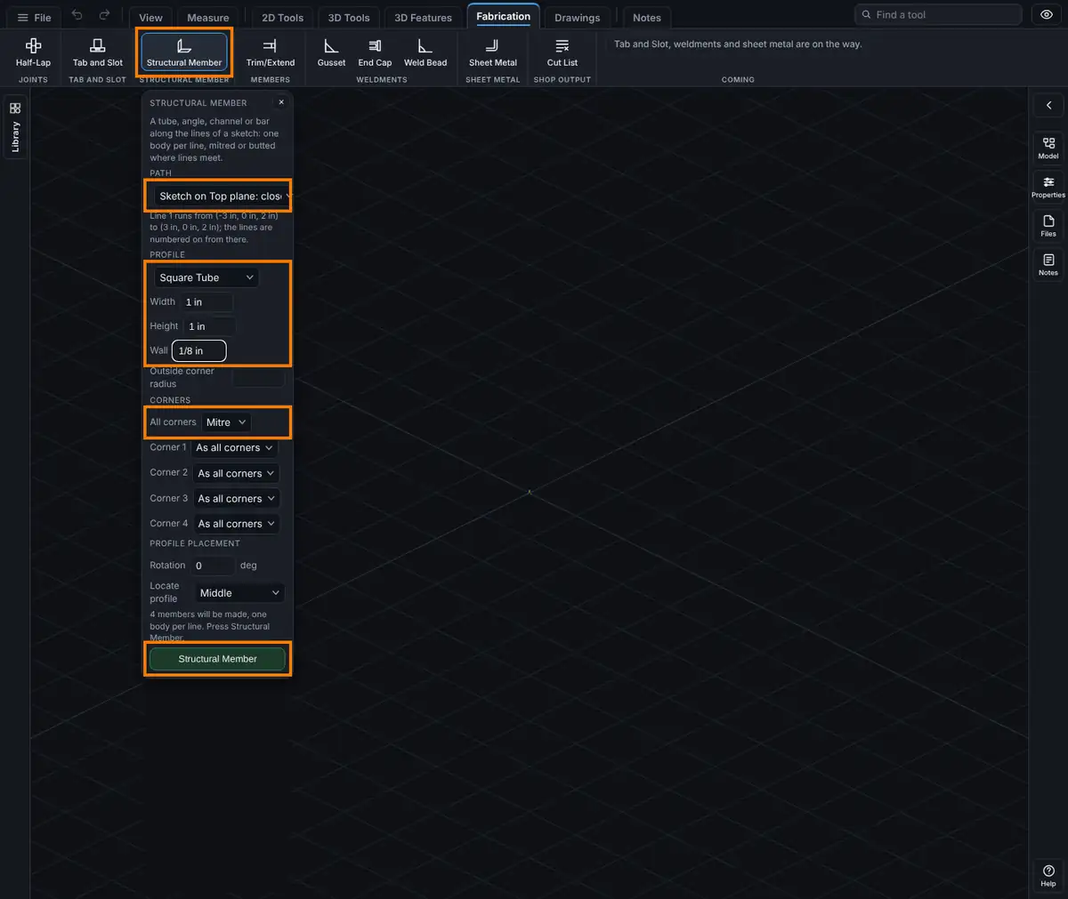
- Under Path, choose the sketch. You can also click the sketch in the Model tree. The panel shows where line 1 starts; the lines are numbered on from there along the path.
- Under Profile, choose the stock and type its sizes in any unit (2 in, 50 mm, 1 3/8). The boxes are the same as in the Parts Library. Or choose one of your own profiles, listed after the shipped stock; its sizes come with it.
- Under Corners, choose how the members meet: Mitre, Butt 1 or Butt 2. To treat one corner differently, change its own Corner list.
- Set the Rotation and Locate profile if the stock should sit off center or turned.
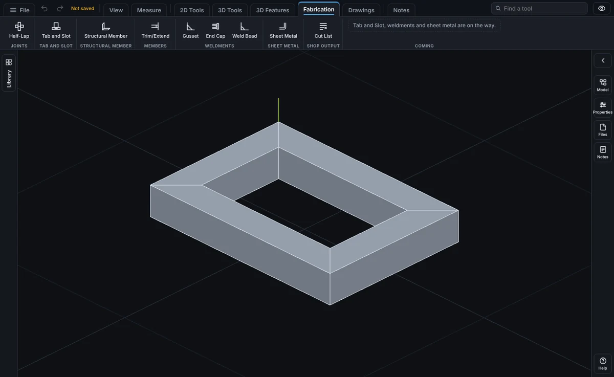
- Click Structural Member. One body is made for each line, named Member 1, Member 2 and so on, and a message such as "Structural Member: 4 members made, one body each." gives the volume of the part.
Options
- Path: the sketch whose lines the members follow. Only sketches made of straight lines are listed.
- Profile: the stock, from the Parts Library: Square Tube, Rectangular Tube, Round Tube, Angle, Channel, Flat Bar, Round Bar or Square Bar. A plate is not a member. After them come your own profiles from My profiles in the Parts Library, each named with "(my profile, ...)" after it.
- Sizes: the same boxes as the Parts Library, without the length (each member is as long as its line). A corner radius box left empty makes square corners.
- All corners: how every corner is cut. Mitre cuts both members on the line that halves the corner, as a picture frame. Butt 1 runs the earlier member along the path (line 1 before line 2, line 2 before line 3, and so on; the panel shows where line 1 starts) through to the far side of the later one, and cuts the later one flush against the side of the earlier one. At a right angle both cuts are square; at other angles they lean to lie flush. Butt 2 does it the other way round. Where two lines run on in a straight line, the members meet square whatever this says.
- Corner 1, Corner 2, ...: one list per corner, where line 1 meets line 2, and so on. As all corners uses the choice above; Mitre, Butt 1 or Butt 2 overrides it for that corner only. A closed path has one more corner, where the last line meets the first.
- Rotation: turns the profile about each line, in degrees, from -360 to 360. At 0 the profile's height (H, leg A, the channel depth) stands up out of the sketch plane.
- Locate profile: the point of the profile's outline box that sits on the line: the Middle, a side (Bottom middle, Top middle, Middle left, Middle right) or a corner (Bottom left, Top right, ...). Top is out of the sketch plane, and left and right are as you look along the line from its start. The member then lies on the other side: with Middle right it lies to the left of the line. For a frame drawn counterclockwise (seen from above the sketch), Bottom right or Middle right keeps the tube inside the lines, so the outside of the frame is on the lines you drew.
Your Own Profiles
The Profile list also offers your own profiles from My profiles in the Parts Library (see My Profiles in the Parts Library). They are saved with the part, so the list shows the profiles of the part you have open.
- Add the profile first: open the Library drawer, click New profile... under My profiles, and make a rectangular tube, angle, channel, round tube or custom outline.
- Open Structural Member, pick the path, and under Profile choose your profile. It is listed after the shipped stock, with "(my profile, ...)" after its name.
- A line under the list shows what the profile is. Its sizes come from the profile and cannot be typed here; for another size, add a new profile.
- Set the corners, Rotation and Locate profile as usual, and click Structural Member.
What to expect:
- A rectangular tube, angle, channel or round tube profile builds exactly as the shipped stock of the same sizes. A custom outline builds its outline along each line, centred on the box round its corners, with "across" running across the line and "up" out of the sketch plane; its box stands in for the stock's box in Locate profile and in the Butt 1 and Butt 2 cuts.
- The History row names your profile, for example "Structural Member: Stair rail (custom outline, 6 corners), 4 members, Mitre", and so does the Cut List.
- The step keeps the sizes (or the corners) and the profile's name, so renaming or deleting the profile later never changes the members, and the part saves and opens again the same. It is one step, and one Undo.
- If the profile you picked last was deleted, the panel goes back to Square Tube and a message says so. Pick another profile from the list. A new profile never takes the place of a deleted one, so the panel never picks a different profile by mistake. When you open another part, the panel starts on Square Tube, since each part has its own profiles.
Worked Example
A 50 x 50 x 3 mm square tube on an L of a 1000 mm line and a 600 mm line, mitred, makes two members with 1000 mm and 600 mm of center line. The first is cut 1025 mm long at its outside edge (0 and 45 degrees), the second 625 mm. With Butt 1 the first runs through to 1025 mm with square ends and the second is 575 mm; with Butt 2 the first is 975 mm and the second 625 mm. A closed 1000 x 600 mm rectangle mitred all round is four members, two of 1050 mm and two of 650 mm, each 45 degrees at both ends.
Edit It Later
Right-click the step in the Model tree and choose Edit Feature to change the corner for every joint, the Rotation and Locate profile. To change the stock or the path, delete the step and make it again from the sketch, which is still in the Model tree.
Limits
- Straight lines only. A path with an arc or a curve is refused; for a bent member use Sweep.
- One sketch, flat on its plane. 3D sketches are not taken yet.
- At most 50 lines in one step. Make a bigger frame in more steps.
- Corners join two members only. A point where three lines meet, or lines that cross, cannot be one path; draw each run in its own sketch and use Trim/Extend where the runs meet.
- No end caps, gaps at the corners or merged arc corners yet. Add an End Cap, a Gusset or a Weld Bead as their own steps.
- Moving the sketch afterwards does not move the members. Make the step again after editing the path.
- The Cut List follows a later Trim/Extend To a face or Mitre of a member. A member fitted To a body is listed under Not listed: check that length by hand. Copies made by a Pattern of the step are not listed yet.
Tips
- The members are new bodies, never joined to the part already there, so they can overlap a plate or a block you drew. Use Combine if you want them as one body.
- Locate profile on a right or left point keeps the tube to one side of the lines you drew, so the outside (or the inside) of the frame matches the drawing. Try one, and change it with Edit Feature if it lands on the wrong side.
- The Cut List groups members of the same stock, length and angles into one row with a quantity. Members made from two of your profiles are never one row, even when their sizes match, and neither are a profile and the shipped stock or two tubes with different corner radii.
Common Mistakes and Messages
- The path list is empty: the sketch has an arc, a curve or a circle, or is still open for drawing. The panel says "Pick the path: a sketch of connected straight lines. Draw it, then Exit Sketch." Click Exit Sketch, and draw the frame with straight lines.
- "The path is broken between line 2 and line 3. Join their ends in the sketch." Two lines do not meet end to end. Drag the end of one onto the other.
- "At corner 2 the path turns back on itself (170 degrees, more than 165), so the members would run into each other. Open the corner up." Two lines meet at a very sharp point. Open the corner up.
- "Corner 1 turns only 10 degrees, too little for a butt joint (15 at least). Choose Mitre for that corner." Choose Mitre for that corner in its own Corner list.
- "Line 2 is too short for its corners: the cuts at its two ends would cross. Make the line longer, or choose other corners." The line is shorter than the stock is wide. Make the line longer or the stock smaller.
- "Members 1 and 3 would overlap by ... cubic mm: the path crosses itself or comes back too close." Draw a path that does not cross, or make crossing runs in separate steps.
Related Tools
- Parts Library: drop one length of stock anywhere
- My Profiles in the Parts Library: your own stock sizes and outlines
- Sweep: a profile along a path with arcs, as one body
- Cut List: the cut lengths and angles of every member
- Trim/Extend: cut a member back or run it on to meet another
- Weld Bead and Gusset: finish the joints