Make Drawing: Detail, Auxiliary and Broken Views
Three more views for a drawing made with Make Drawing (on the Documents tab): a detail view (a circled part of a view drawn bigger), an auxiliary view (the part seen square to a sloped edge, so a slanted face shows at its true size) and a broken view (a long part drawn shorter, with a piece taken out of the middle and its true length written on it). They go on the same sheet and into the same DXF file as the other views.
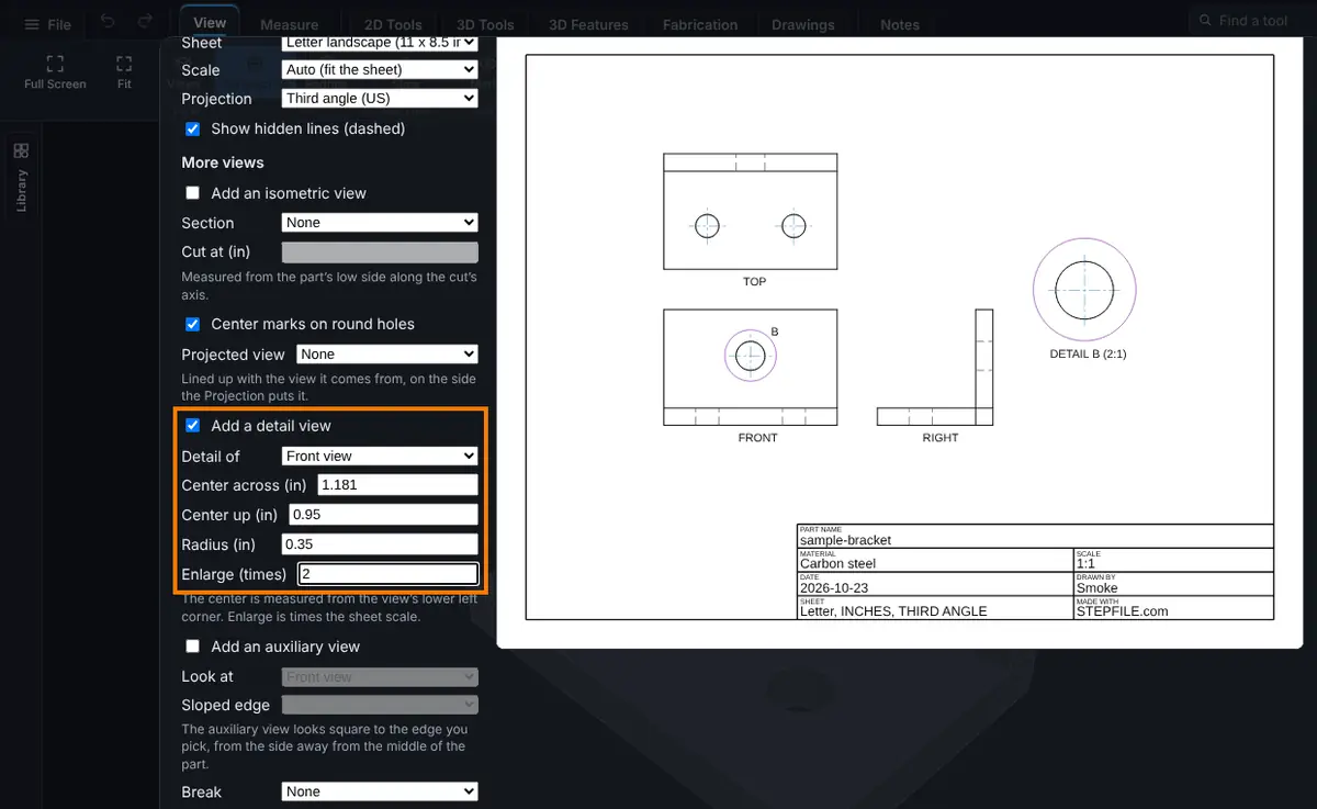
What you get: a circle marked B on the view and the same part of it drawn bigger beside the views as DETAIL B (2:1); or VIEW C, a sloped face seen square on at its true size; or a long part drawn shorter with its true length written on it. All of it is on the same sheet and in the same DXF.
Step by Step
- Open a 3D part, click the Documents tab, then Make Drawing (see Make Drawing).
- For a detail view, click Advanced options at the bottom of the left side of the window, scroll to Add a detail view and tick it. The circle starts on the upper right corner of the Front view. Pick the view in Detail of, type the circle's Center across, Center up and Radius, and how much bigger in Enlarge (times). For the hole in the Front view of the sample bracket that is Center across 1.181, Center up 0.95, Radius 0.35 and Enlarge 2; the line under the settings then ends Detail B of the Front view at 2:1: 37 lines.
- For an auxiliary view, tick Add an auxiliary view. Pick the view in Look at, then the edge in Sloped edge.
- For a broken view, pick an axis in Break, and type where the piece taken out starts and ends in Take out from and Take out to.
- Check the picture. The line under it names each view and counts its lines, or says why a choice cannot be drawn (Download stays off until it can).
- Click Download DXF at the bottom of the window.
Options
- Add a detail view: It starts unticked. When you tick it, the circle starts on the upper right corner of the Front view, with a radius of a quarter of the view's smaller side, enlarged 2 times.
- Detail of: Front view, Top view or Right view. Picking another view puts the circle on that view's upper right corner again.
- Center across and Center up: the circle's center, measured on the part from the lower left corner of the view, in millimeters (mm) or, when your display unit is inches or feet, in inches (in). You can type the unit after the number (12 mm, 2 cm, 0.5 in). The center must be on the view: from 0 to its width across, from 0 to its height up.
- Radius: the circle's radius on the part, in the same unit: from a thousandth of the view's longer side up to all of it.
- Enlarge (times): how many times the sheet scale the detail is drawn, more than 1 and at most 20. You can type 2, 2.5, 2x or 2:1. The detail's own scale is written under it: on a sheet at 1:1, Enlarge 2 gives DETAIL B (2:1); on a sheet at 1:2 it gives DETAIL B (1:1).
- Add an auxiliary view: It starts unticked.
- Look at: Front view, Top view or Right view: the view whose sloped edge the auxiliary view looks square to. It starts on Front view.
- Sloped edge: the edges of that view that are neither level nor upright, longest first, each with its length and its angle in the view (for example Edge 1: 28.284 mm at 135 degrees). The first one is picked for you. At most 40 are listed.
- Break: None, Along X, Along Y or Along Z. It starts on None. When you pick an axis, the piece from 30 to 70 in every 100 of the part's size along it is filled in.
- Take out from and Take out to: where the piece taken out starts and ends, measured from the part's low side along the break's axis (its left end for X, its bottom for Y, its back for Z), in mm or in like the other boxes. Both must be more than 0 and less than the part's size along that axis, and the end must come after the start.
- Each typed box holds at most 24 letters (an emoji counts as one). A box with a hidden or control character in it (such as a zero width space or a direction mark, often picked up with a paste) is refused, so you can clear it and type the number again.
Detail View
- The circle and the letter B are drawn on the view the detail comes from (the circle on layer DETAIL, the letter on NOTES).
- The detail sits right of the three views, with the other extra views. Its lines are the view's own lines inside the circle, drawn bigger, inside a circle of their own. Hidden lines and center marks inside the circle come with it.
- It is labelled with its own scale, such as DETAIL B (2:1).
Auxiliary View
- A sloped edge in a view is often a slanted face seen edge on. The auxiliary view looks straight at that face, so the face shows at its true size and shape.
- It looks from the side of the edge away from the middle of the part. The direction the view you picked looks from points up in it: for an edge of the Front view, the front of the part is at the top.
- An arrow marked C on the view points the way it looks (layer ARROW), and the view is labelled VIEW C. Hidden lines are dashed when Show hidden lines (dashed) is ticked.
Broken View
- The front, top and right views that show the break's axis along them are drawn with the piece taken out: the far end is moved up to the near end, with a small gap (a twentieth of the part's size, or half the piece taken out if that is less).
- A break line with a zig zag in the middle is drawn at each side of the gap (layer BREAK).
- The part's true length is written on a dimension line beside the view (layer DIM): under the Front view for a break along X, under the Right view for a break along Z, and beside the Front view for a break along Y (left of it in third angle, right of it in first angle, the number turned upright). It is in mm on an A4 or A3 sheet and in inches on Letter or Tabloid.
- Lines and center marks past the gap move with the far end; the ones in the piece taken out are left out.
Limits
- One detail, one auxiliary view and one break on a sheet. The letters are always B (detail) and C (auxiliary view).
- The detail circle is placed by typing its center and radius; you cannot drag it on the picture yet. A detail of the isometric, section or auxiliary view is not offered.
- The auxiliary view sits with the other extra views right of the three views, not lined up with its edge. It always looks from the side away from the middle of the part. Only a sloped edge of the Front, Top or Right view can be picked, not a face in the 3D view. Short edges (under 2 in 100 of the view's longer side) are not listed, and a round hole seen end on can list some of its many short sides.
- Only the front, top and right views are broken; the isometric, section, detail and auxiliary views show the whole part. One piece is taken out, square to X, Y or Z.
- A broken view and a section view cannot be on one sheet yet. A detail or an auxiliary view cannot be taken from a view that is broken: take it from another view, or set Break to None.
- The true length on a broken view is the only dimension on the sheet. The arrow and letters can sit close to other lines on a busy view.
- The circles are written as 72 short straight lines each.
- On a broken view, a note or balloon points at the same place on the part, moved up by the piece taken out. When the place it would point at is in that piece, it is refused: move the break, or point it at another view.
- If the view's label (such as FRONT) is in the way of the auxiliary arrow, it moves to one side of the arrow.
- All the extra views go in the column right of the three views: with several of them, Auto may pick a smaller scale, or pick a bigger sheet.
- The time and size limits of Make Drawing apply.
Common Mistakes and Messages
- "... has a hidden or control character in it." Clear the box and type the number again.
- "... is not a number." Type a number, or a number and mm, cm or in.
- "Center across must be from 0 to ..." or "Center up must be from 0 to ..." Type a place on the view.
- "The radius must be from ... to ..." Type a radius between the two sizes the message gives.
- "A detail enlarged 25 times is not offered. Type a number more than 1 and at most 20, such as 2 for twice the sheet scale." Type a number more than 1 and at most 20.
- "The detail circle has none of the ... view's lines in it. Move its center or make it bigger." Move its center onto an edge of the part, or make it bigger.
- "The ... view has no sloped edge (one neither level nor upright), so there is nothing for an auxiliary view to look square at." Pick another view in Look at, or untick Add an auxiliary view. A plain box or an L bracket like the sample has no sloped edge in any view.
- "That edge is level or upright ..." Pick a sloped edge.
- "A break from 0.709 to 0.1 in does not fit." Type a start and an end inside the part, the end after the start.
- "A broken view and a section view cannot be on one sheet yet." Set Section or Break to None.
- "The detail view is taken from the ... view, which is broken." or "The auxiliary view looks at an edge of the ... view, which is broken." Pick another view, or set Break to None.
- "At ... the views need ..." The extra views do not fit at that scale. Pick Auto, a smaller scale or a bigger sheet.
Tips
- A detail is handy for a small feature on a big part: a small hole, a groove, a chamfer. Put the center on the feature and keep the radius small.
- For a part with a chamfer or a slanted face, pick the edge that is the face seen edge on; the auxiliary view then shows the face flat.
- A long bar, tube or rail fits a bigger scale when broken: take out the plain middle and keep the ends with the holes.