Symmetric Mate
Makes two entities mirror images of each other across a plane.
What you get: the two entities held as mirror images of each other across the plane, and one mate named Symmetric1 in the Mates folder of the Model tree.
When to Use It
- Keep two arms the same distance from a center plane
- Hold two holes mirrored about a plane
- Keep a pair of parts symmetric while one is moved
Step by Step
- Open an assembly (assemblies need the Pro plan) with at least two components in it. See Assemblies: Start and Insert Parts.
- Click Mate on the Assembly tab (or right-click a component and choose Assembly tools, Mate...), then click the Advanced tab at the top of the window.
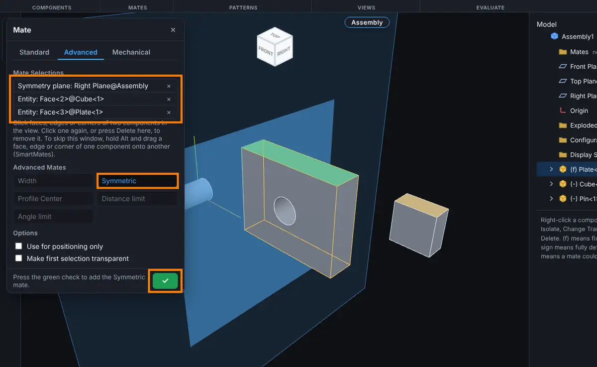
- Click the symmetry plane first. It can be a flat face, or the Front Plane, Top Plane or Right Plane row in the Model tree. It shows as Symmetry plane.
- Click one entity on one component, then the matching entity on a different component. Each shows as Entity. The two must be the same kind, for example two flat faces or two corners.
- Click Symmetric. It is lit when the picks fit.
- Click the green check to add the mate. The message reads "Symmetric1 added."
Options
- Symmetric has no value or alignment choice.
- Use for positioning only and Make first selection transparent work as on the Standard tab.
Tips and What to Expect
- The two entities must be on different components.
- The mate keeps the two entities mirrored. The parts can still slide along the plane, so add other mates to finish positioning.
Common Mistakes and Messages
- Symmetric stays grey. The two entities are not the same kind (a face and a corner), or the plane was not picked first. Remove the picks and start with the plane.
- Every button is grey. The picks do not fit any mate on this tab. The status line says what is missing, for example "Pick more entities." Remove a pick (click it again or press Delete in Mate Selections) and try again.
- "Collapse the exploded view to add mates." Mates cannot be added while the assembly is exploded.
- The Over defined prompt appears. The new mate conflicts with the ones already there. See Mates: Fixing Mate Problems.