Round and Chamfer (Edges)
On the Features tab, Round works on the solid part's own edges (compare Sketch Corner, on the Sketch tab, which rounds or chamfers a sketch's corners instead). A round is also called a fillet.
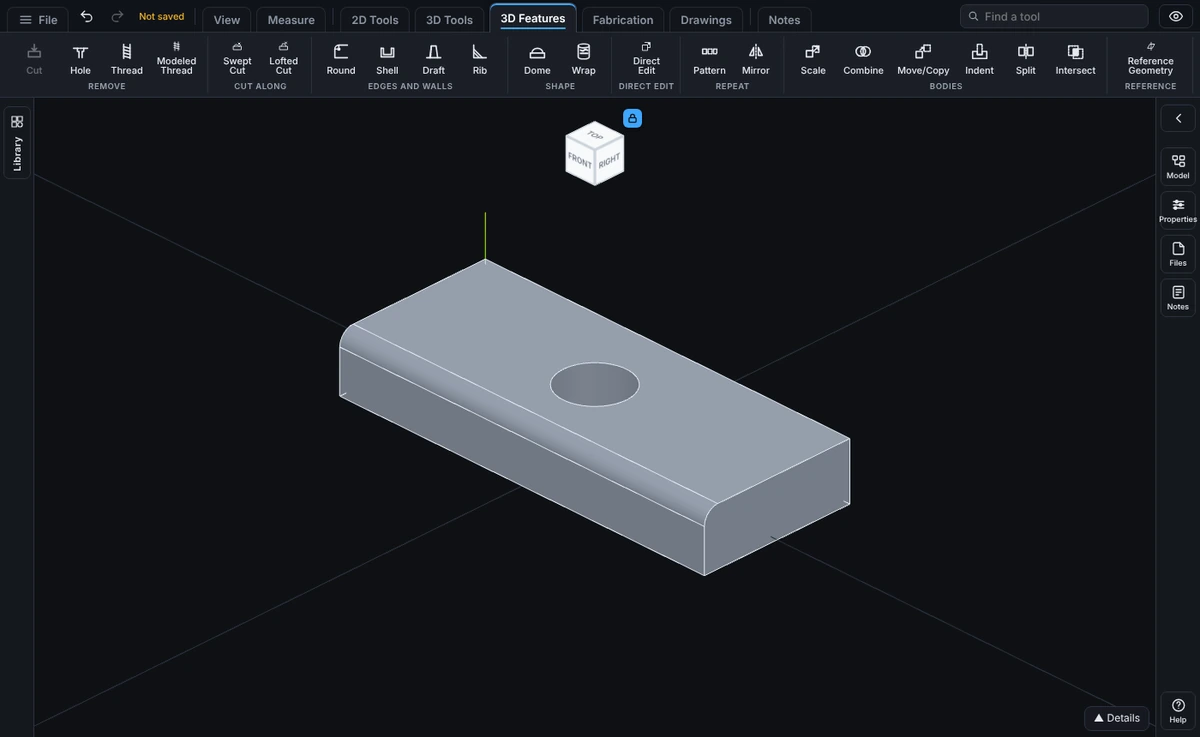
What you get: each edge you picked rounded to the size you typed (or cut off flat for a chamfer), as one step in the Model tree that one Undo takes back.
Step by Step: Round an Edge (Fillet)
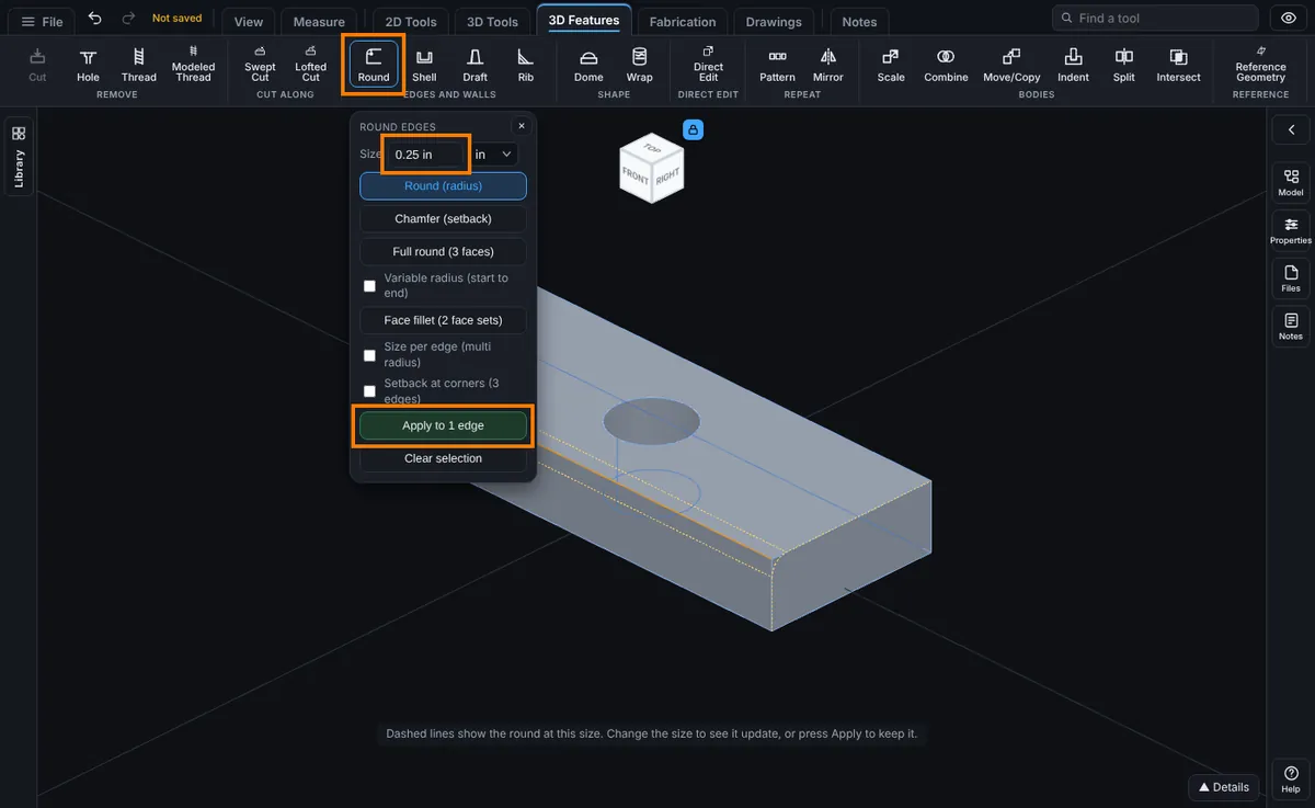
- Open or build a solid part. Click the Features tab, then Round. The Round Edges panel opens, ready for edge clicks.
- Keep Round (radius) chosen and type the radius in Size, like
0.25 inor6 mm. - Click each edge of the part to round. A picked edge lights orange and the button at the bottom reads Apply to 1 edge (then 2 edges, and so on). Click a lit edge again to drop it.
- Dashed lines show the round at this size. The hint under the view says "Dashed lines show the round at this size. Change the size to see it update, or press Apply to keep it."
Step by Step: Apply the Round
- Press Apply to 1 edge. The edge is rounded, a message says how many edges were rounded and the new volume, and the step shows in the Model tree.
- To change the size later, right-click the step in the Model tree and choose Edit Feature.
How to Start It
Click Round. It arms ready to take edge clicks right away; the Round and Chamfer buttons only say which kind is applied.
What to Pick
- Size: radius for Round, setback along each face for Chamfer. Type any unit to override your display unit.
- Round (radius), Chamfer (setback) or Full round (3 faces) (see Full Round below)
- For a Chamfer, choose its type (below)
- Click each edge of the part to add it (each click adds one; a lit edge clicked again drops it)
- Apply to commit, or Clear selection to start over without applying
Step by Step: a Chamfer
- On the Features tab, click Round, then click Chamfer (setback).
- Choose the type: Equal distance, Angle-Distance, Distance-Distance or Corner (vertex).
- Type Size. For Distance-Distance also type Distance 2. For Angle-Distance also type Angle.
- Click the edge of the part to chamfer. For a corner, click near the end of an edge at that corner. The button now reads Apply to 1 edge, or Apply to 1 corner.
- Dashed lines show the chamfer at this size. Change a number to see it update.
- Press Apply. If it does not fit, you are told in plain words and the part is left as it was.
Chamfer Types
Choose one of four after you click Chamfer:
- Equal distance: the same setback on both faces (the default).
- Angle-Distance: Size is the distance along one face, and Angle (more than 0 and less than 90 degrees, 45 by default) is how steeply the chamfer leans away from that face. Flip direction runs the distance along the other face.
- Distance-Distance: Size is the first distance and Distance 2 the second, one on each face. Flip direction swaps them.
- Corner (vertex): click near the end of an edge to pick the corner at that end, then type three distances (one along each of the corner's three edges), or tick Equal distances to use Size for all three. The corner is cut off flat.
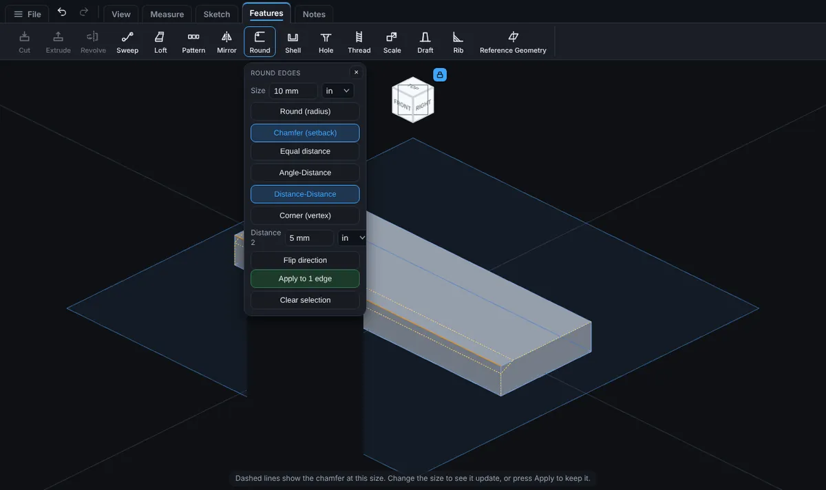
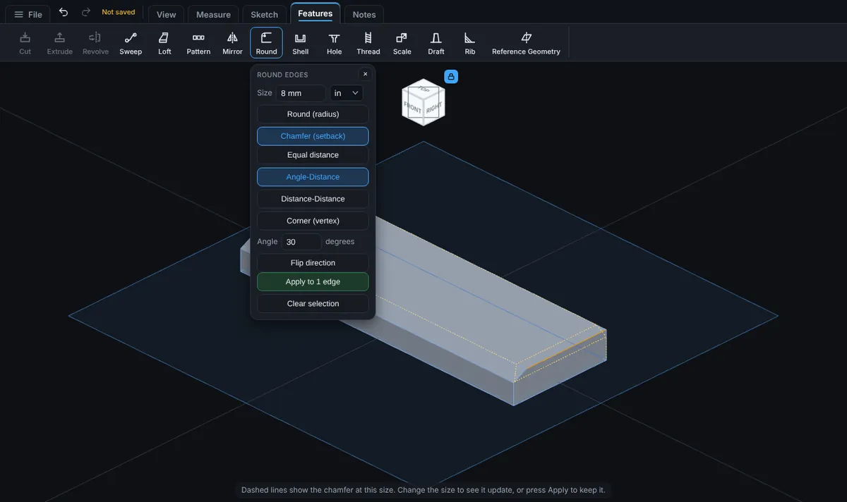
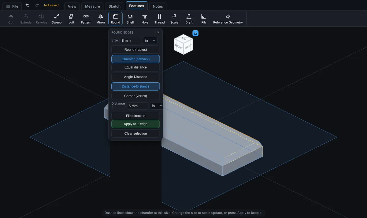
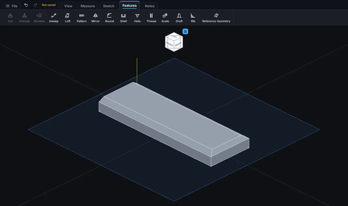
Which face gets the first distance: the larger of the edge's two faces. If both are the same size, Flip direction lets you choose. It never depends on where you clicked, so the step rebuilds the same way every time. If it is the wrong way round, tick Flip direction.
In the Model tree, the step reads like Chamfer 2 edges, 0.1 in x 45°, Chamfer 2 edges, 0.1 in x 0.2 in or Chamfer corner, 0.1 in. Edit Feature changes the type, the distances, the angle and the flip.
If a distance is too big for the faces, or the angle is not between 0 and 90, you are told in plain words and the part is left as it was.
Full Round
Full round (3 faces) turns the end of a bar, rib or tab into a half round. You pick three faces and the middle one is replaced by a rounded surface that touches both of the others smoothly. There is no radius to type: the round is half the width of the middle face.
- Click Round, then click Full round (3 faces).
- Click a side face of the part (it lights orange).
- Click the centre face, the one to be rounded (it lights pink).
- Click the side face on the other edge of the centre face (orange).
- Dashed lines show the full round. Press Apply full round, or click a lit face to drop it and choose another.
What it needs: three flat faces. The two side faces must face away from each other and be square to the centre face, like the two sides of a bar, and the centre face must be a plain rectangle. The sides must be at least half the centre face's width deep, or the round would run past the bottom of them. If the faces will not do, the hint under the toolbar says why in plain words (the faces are not next to each other, not opposite each other, the centre face is too wide for the sides, or a face is curved) and the part is left as it was. A view only share cannot make one.
In the Model tree, the step reads Full round, 3 faces. It is one step, so one Undo takes it back, and it is saved and rebuilt with the rest of the history. There is no size to change with Edit Feature; delete the step and make it again to choose other faces.
Variable Radius
A round whose size changes along the edge: one radius at the start of the edge, another at its end, blending evenly between them.
- On the Features tab, click Round. Keep Round (radius) chosen.
- Tick Variable radius (start to end). The Size box now reads Start size, and an End size box appears.
- Type Start size and End size. Both must be more than zero.
- Click the edges to round. A green dot marks the start of each picked edge.
- Dashed lines show the round. Change a size to see it update.
- To make the other end the start on every picked edge, press Swap ends. The green dots move.
- Press Apply. It is one step in the Model tree and one Undo.
Which end is the start: the end of the edge with the lower X; if both ends have the same X, the lower Y; then the lower Z. It never depends on where you clicked, so the step rebuilds the same way every time.
In the Model tree the step reads like Round 2 edges, 2 mm to 6 mm. Edit Feature changes the start size, the end size and Swap ends.
Limits and problems:
- The larger of the two sizes must fit along the whole edge as a plain round. If it does not, you are told in plain words and the part is left as it was. Try smaller sizes.
- An edge that is a closed loop, such as the rim of a hole or a circle, has no start or end, so it is refused. Round it with one radius instead.
- Edges that meet at a corner are refused in one variable radius step. Round them as separate steps, or use one radius for them. The order you click the edges never changes the result.
Face Fillet
Round the corner between two sets of faces, without picking the edges one by one.
- On the Features tab, click Round, then click Face fillet (2 face sets).
- Type Size, the radius.
- Pick Set 1 is chosen. Click the faces of the first set. They light orange.
- Press Pick Set 2 and click the faces of the second set. They light blue.
- A lit face clicked again is dropped. Clear faces drops them all.
- Dashed lines show the round on every edge where a face of Set 1 meets a face of Set 2. Press Apply face fillet. It is one step in the Model tree and one Undo.
For example, the top face as Set 1 and the four sides as Set 2 rounds the whole top rim in one step.
In the Model tree the step reads like Face fillet, 3 mm, 1 face to 4 faces. Edit Feature changes the radius.
Limits and problems:
- The two sets must touch along an edge. Faces that do not touch (with a gap between them) are refused in plain words: this version cannot grow a round across a gap. Pick faces that share an edge, or use Round on the edges.
- A face can be in one set only. All faces must be on the same body.
- Where the two sets already blend smoothly into each other there is no corner to round, and you are told so.
- A radius too large for the faces is refused, and the part is left as it was.
- A view only share cannot make either kind of round.
Size per Edge (Multi Radius)
Round several edges in one step, each at its own size.
- On the Features tab, click Round. Keep Round (radius) chosen.
- Tick Size per edge (multi radius). The Size box now reads Size for new edges.
- Type a size, then click the edges that take it. Each new edge takes the size in the box when you click it.
- Type another size and click the next edges, and so on.
- A list under the checkbox shows Edge 1, Edge 2 and so on, each with its own size box. Click in a box to light that edge green on the part, and type to change its size. A lit edge clicked again on the part is dropped from the list.
- Dashed lines show the rounds. Press Apply. It is one step in the Model tree and one Undo.
Edges of the same size are rounded together, so where they meet at a corner they blend exactly as one plain round. The sizes are rounded one after the other, the largest first. The order you click the edges never changes the result. If every edge has the same size, it is exactly the plain round.
For example, on a block: the four upright edges at 0.2 in (5 mm) and the four edges of the top rim at 0.08 in (2 mm). The rim runs on around the upright rounds.
In the Model tree the step reads like Round 8 edges, sizes 0.08 in and 0.2 in (or 2 mm and 5 mm in millimetres). Edit Feature shows one size box per edge.
Limits and problems:
- Where edges of different sizes meet at a corner, the larger round can carry the smaller one on into an edge you did not pick, or into an edge you gave another size. That step is refused in plain words and the part is left as it was. Give the edges that meet at that corner the same size, or also pick the edges that run on from them (as in the block above).
- A setback works with one size for every edge, so it is not available with Size per edge. To set back a corner, turn Size per edge off and tick Setback at corners (3 edges) (see below).
- Size per edge and Variable radius are one or the other: ticking one clears the other.
- Every size must be more than zero. An empty or bad size box is named in the hint (Type a size for edge 2), and Apply stays off until it is fixed. With every row filled in, Size for new edges may be left empty.
- A size too large for its edge is refused, and the part is left as it was.
Setback at Corners
Where three rounded edges meet at a corner, a setback makes each round keep its full size until a set distance from the corner, and then blends the corner smoothly between them. A larger setback gives a broader, softer corner.
- On the Features tab, click Round. Keep Round (radius) chosen.
- Type Size, the radius.
- Tick Setback at corners (3 edges). A Setback box appears. Type how far from the corner each round starts to blend into the others. It must be more than the Size.
- Click the three edges that meet at the corner, and any other edges to round in the same step.
- To give an edge its own setback, tick Setback per edge. A list shows Edge 1, Edge 2 and so on. Type a distance in an edge's box. A blank box takes the Setback above.
- Dashed lines show the rounds. Press Apply. It is one step in the Model tree and one Undo.
Every corner where three of the picked edges meet is set back. Other corners are rounded as the plain round rounds them. Pick all twelve edges of a block to set back all eight corners.
What the corner looks like: each round runs at its full size up to its own setback, then rolls onto a ball of the same size. Between the three rounds a small flat face is left, rounded all the way round, and every face meets the next smoothly, with no crease. The order you click the edges never changes the result.
For example, on a block: the three edges of one corner at 0.25 in (6 mm) with a setback of 0.5 in (12 mm).
In the Model tree the step reads like Round 3 edges, 0.25 in, setback 0.5 in or, with a setback per edge, Round 3 edges, 0.2 in, setbacks 0.5 in, 0.6 in and 0.8 in (or 5 mm, setbacks 12 mm, 15 mm and 20 mm in millimetres). Edit Feature changes the size, the setback and each edge's own setback.
Limits and problems:
- Only a box corner can be set back: three straight edges at right angles to each other, no other edge at that point, and the part inside the corner (an outside corner, like the corner of a block). Any other corner is refused in plain words. Turn Setback off to round it.
- Every setback must be more than the Size (at least 1.02 times it).
- At one corner, how far each setback reaches past the Size may differ at most ten times between the three edges. If the distances are further apart than that, you are told to bring them closer together.
- A setback must fit along its edge with room for the round. An edge set back at both of its ends needs room for both.
- The part must be solid inside the corner as far as the setback reaches. A hole, a pocket or another round in the way is refused.
- At least one corner must have three picked edges. If none has, the step is refused: pick the three edges of a corner, or turn Setback off.
- A setback works with one size for every edge. Setback at corners, Variable radius and Size per edge are one or the other: ticking one clears the others. A setback is for rounds, not chamfers.
- Every setback corner is checked by its volume before it is kept. A corner that does not come out as a clean blend is refused, and the part is left as it was.
- A view only share cannot set back a corner.
Common Mistakes and Messages
- "No edge there. Click closer to a highlighted line." The click was not on an edge. Zoom in and click right on the line.
- "Click at least one edge first." No edge is picked yet. Click the edges to round before you press Apply.
- "Set a positive size." The Size box is empty, zero or not a number. Type a size more than 0, like
0.125 in. - "That radius is too large for at least one of the selected edges. Try a smaller size, or select fewer edges." The round does not fit the faces beside the edge. Type a smaller Size. The part is left as it was.
- "That round took too long to work out, so nothing was changed. Try fewer edges or a simpler part." Round the edges in two or more steps.
- "The chamfer angle must be more than 0 and less than 90 degrees." For Angle-Distance, type an angle such as 30 or 45.
- "Type the second distance." Distance-Distance needs Distance 2 as well as Size.
What You See
Each picked edge is smoothed into a rounded fillet (Round) or a flat angled cut (Chamfer) at the size you typed. The step appears in the Model tree, named for what it did (Round or Chamfer) and how many edges.
Tips
- Multiple edges can be picked and applied together in one step, at the same size.
- To give edges different sizes in one step, tick Size per edge (multi radius) (see above). Or apply the first set, then open Round again for the next size.
- For a softer corner where three rounded edges meet, tick Setback at corners (3 edges) (see above).