Up To Next
An end condition for Extrude and Cut. Instead of typing a depth, you tell the feature to stop at the first face it meets. Each part of the profile runs until it reaches the first solid in its way, so a profile that sits over a stepped part ends on every step at its own height. If the part changes later, the feature follows. For a guided example with pictures, see the Up To Next Walkthrough.
What you get: a boss or cut that stops on the first face it meets, with no depth to type, and the message "Extrusion applied. Volume is now 16.000 in³." (for the example in the pictures). It follows the part when the part changes.
When to Use It
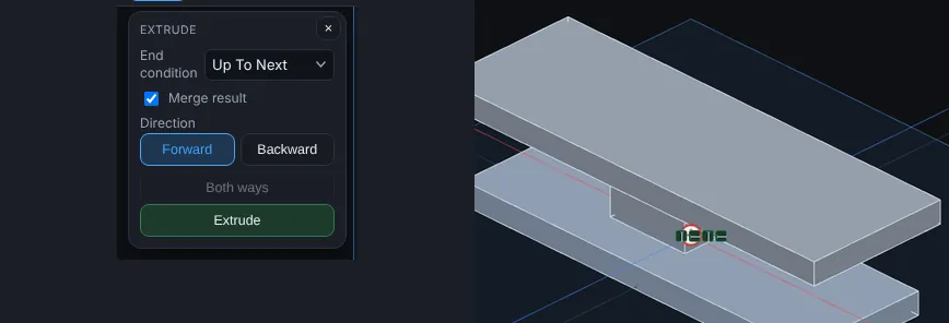
- Fill the gap between two plates without measuring it
- Cut a pocket that stops exactly on the first wall it reaches
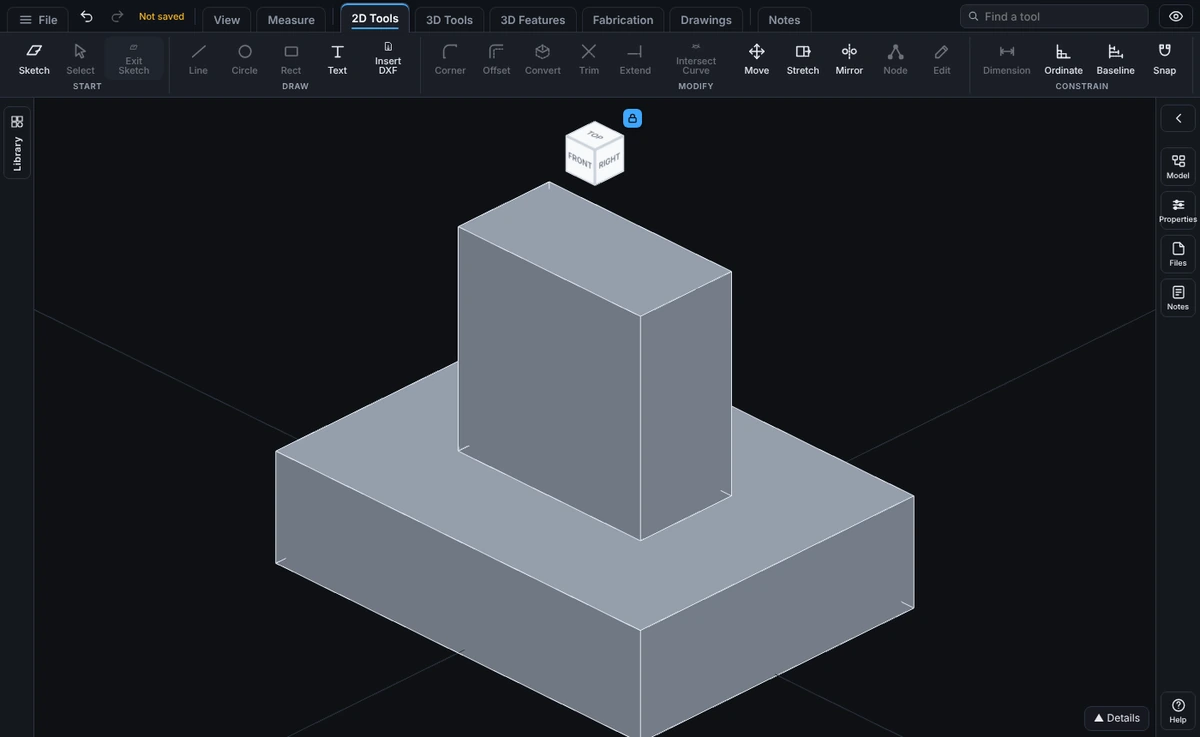
- Build a boss that lands on a stepped or uneven top, with each part ending on its own step
- Keep a feature right when the part below it is made thicker or thinner later
How It Works
The profile is carried in the direction you choose until it meets a face of the existing part. Each separate piece of the profile is measured on its own, so one rectangle can end on two different heights. Extrude looks at every body in the part. Cut looks only at the bodies it works on (see Bodies to cut on the Extrude and Cut page).
For example, a rectangle 2 in by 1 in sketched on a plate, with a second plate 2 in higher, becomes a block that fills the gap and stops on the underside of the second plate.
Step by Step
- Open a sketch on a plane or a face and draw a closed profile (see Planes and Faces). Sketching is part of modeling, which comes with the Pro plans.
- Click Extrude (or Cut) on the Features tab.
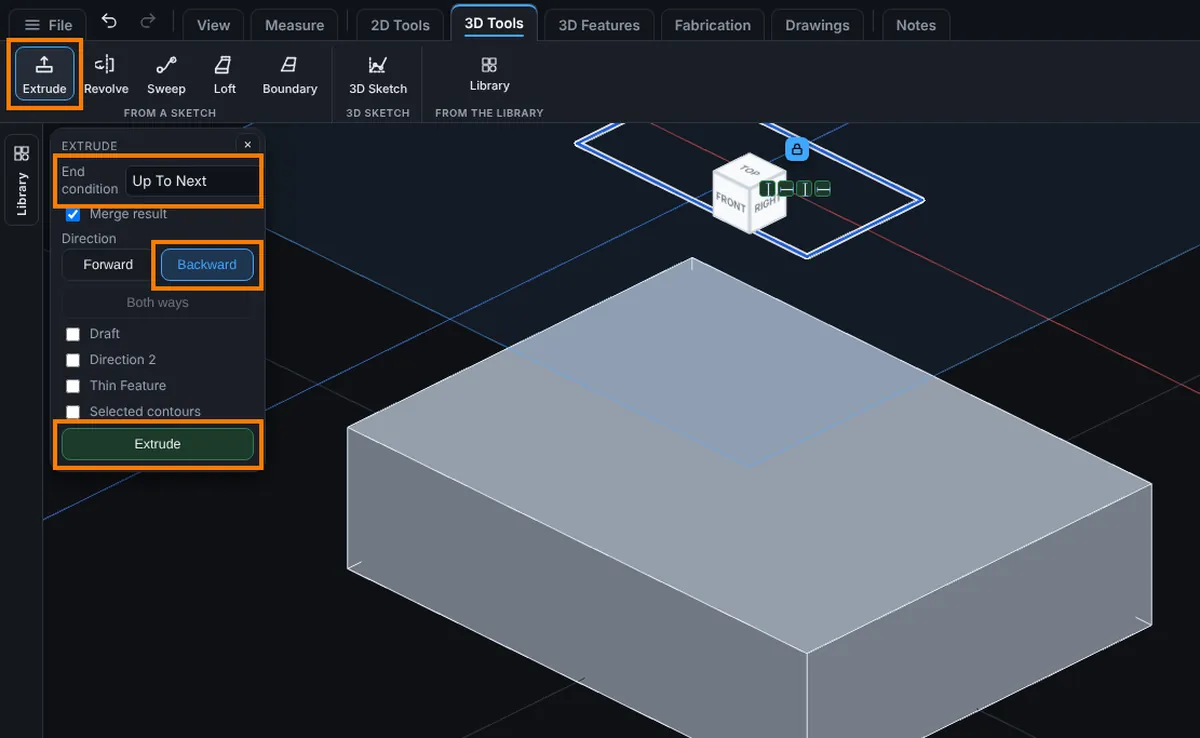
- In End condition, choose Up To Next. The Depth box goes away, because the part decides the depth.
- Choose a Direction: Forward or Backward. Both ways is off for this end condition.
- For Extrude, leave Merge result ticked to join the new material to the bodies it touches, or untick it to keep it as its own body.
- Click Extrude (or Cut). The feature runs to the first face and stops.
- Open the Model tree. The step reads up to next. Its depth is the distance the engine measured.
Options
- End condition: Up To Next. The other choices are Blind (a typed depth), Through All (Cut only) and Up To Surface.
- Direction: Forward or Backward. The first face that way is where the feature ends.
- Merge result (Extrude only): join the new material to the bodies it touches, or keep it separate.
- Bodies to cut (Cut only): the bodies the cut works on, and so the faces it can stop at.
Edit It Later
Right-click the step in the Model tree and choose Edit Feature. You can change the End condition to Blind or Up To Surface, and change Merge result. Changing a plate below the step in the Model tree makes the step follow it. The step does not stay at the old distance.
Tips and What to Expect
- If part of the profile has nothing to stop at, the feature is refused with this message: Up To Next: part of the profile has no face to stop at in this direction. Choose Backward, change the profile, or pick a face with Up To Surface. Nothing is added. Try the other Direction, move the profile so all of it is over the part, or use Up To Surface.
- Up To Next needs a part to end on. Make the first solid with a plain depth.
- If nothing lies between the sketch and the end, there is nothing to add or cut, and a message says so.
- A Pattern can repeat an Up To Next step. Every copy looks for its own first face, so the copies of one boss can end at different heights. A copy with no face to stop at is refused by its number, for example Copy 3 of 3 cannot be made. followed by the reason, and nothing changes.
- An older version of the viewer opens the step as a plain depth (the farthest distance measured here). When the end is flat, square to the direction and joins the part, the shape is the same. Otherwise it can differ, so open such models in this version.
Common Mistakes and Messages
- "Up To Next: part of the profile has no face to stop at in this direction. Choose Backward, change the profile, or pick a face with Up To Surface." Part of the outline hangs past the part. Try the other Direction, or move the outline over the part.
- There is no part yet. Up To Next needs a part to end on. Make the first solid with a plain depth.
- Both ways is greyed out. Up To Next runs one way only. Choose Forward or Backward.
- "Flip side to cut with Up To Next: no part starts at the sketch in this direction, so there is no face to cut up to. Sketch on the part, choose Backward, use a depth or Through All, or pick a face with Up To Surface." A flipped cut needs its sketch on the part.