Parallelogram
Draws a four sided shape whose opposite sides are parallel, with no right angle needed. You click three corners and the fourth is worked out.
When to Use It
- A slanted plate, a link or a rib seen from the side
- A rhombus or a diamond
- Any shape that is a rectangle pushed over
Step by Step
- Open a sketch on a plane or a face (see Planes and Faces). Sketching is part of modeling, which comes with the Pro plans.
- On the Sketch tab, click Rect. In the flyout, click Parallelogram.
- Click the first corner.
- Click the second corner. This is the end of the first side. A dashed line shows it.
- Click the third corner. This is the far end of the second side. A preview shows the whole shape, with the fourth corner worked out so the opposite sides are parallel and equal.
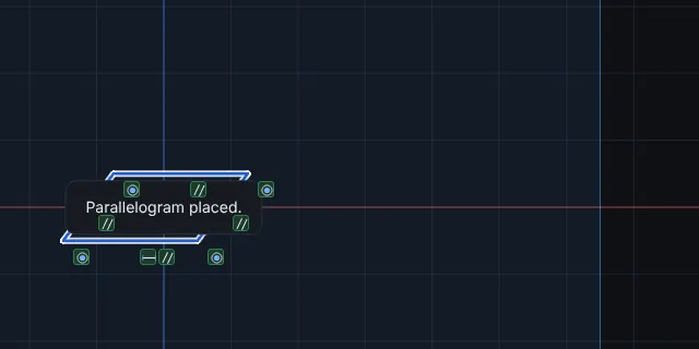
- The parallelogram is placed as four lines joined into one closed outline. A message says Parallelogram placed. Cut or Extrude uses it as one profile. The tool stays armed for another one.
Options
- Construction Geometry: tick the box at the bottom of the Rect flyout first and the shape is drawn as dashed construction geometry. It never cuts or extrudes.
Tips and What to Expect
- The four lines are joined at the corners and the opposite sides are held Parallel, so the shape stays a parallelogram when you drag a corner or a side. See Relations.
- Because it is made of ordinary lines, Smart Dimension works on it: dimension the two side lengths and the angle between them to size it exactly. See Dimensions and Units. There is no typed entry on the tool itself, as there is none on the rectangles.
- Three corners in a line show The three corners are in a line. Move one.
- Corners snap to the grid and to other pieces like other tools. When a side is level or upright, Horizontal or Vertical is added by itself, as for the rectangles.
- Esc after the first or second click cancels. One Undo takes back all four lines and their relations together.