Drawing Weld Symbols
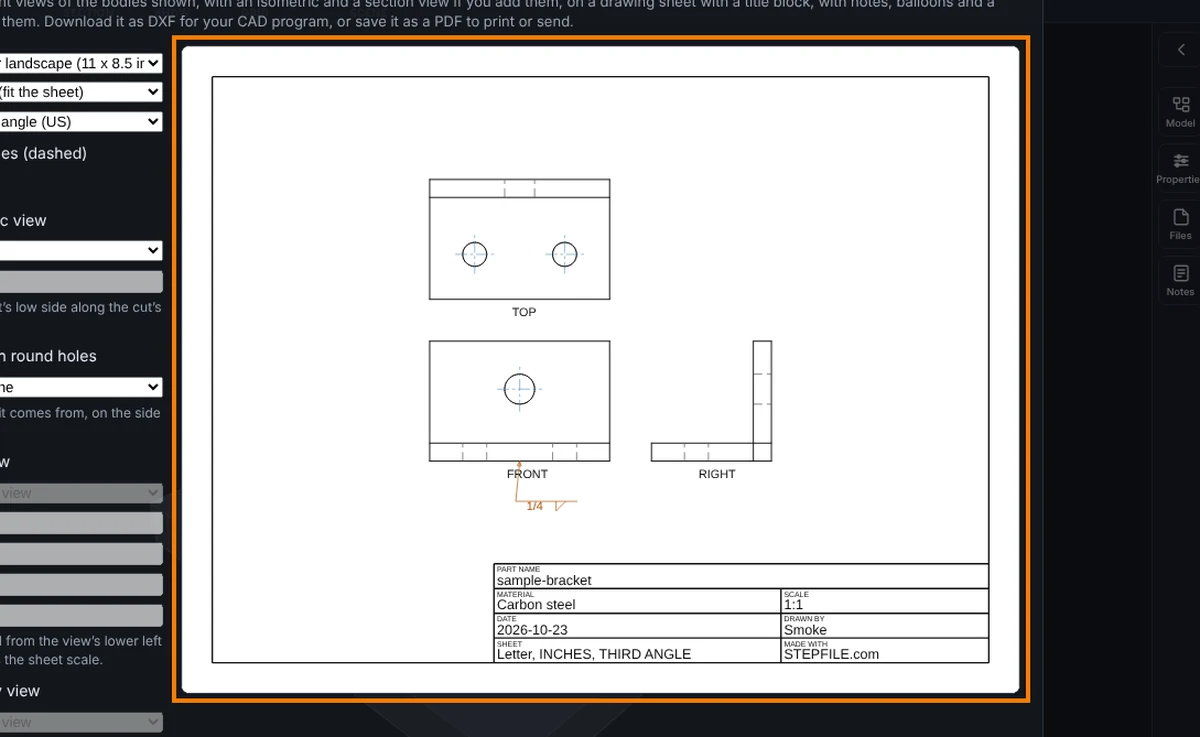
Make Drawing can put weld symbols on the sheet, drawn the AWS way: an arrow to the edge to be welded, a level reference line, the weld's own symbol with its size, length and pitch, and the all around, field weld and tail marks when you ask for them. They go into the DXF on a layer of their own, and Save as PDF draws them on the sheet.
What you get: an AWS weld symbol on the sheet, its arrow on the edge you pick and its size, length and pitch written on it, kept clear of the views and saved in the DXF on the WELD layer.
Step by Step
- Open a 3D part or an assembly, click the Documents tab, then Make Drawing. Set the sheet, the scale and the views as usual (see Make Drawing).
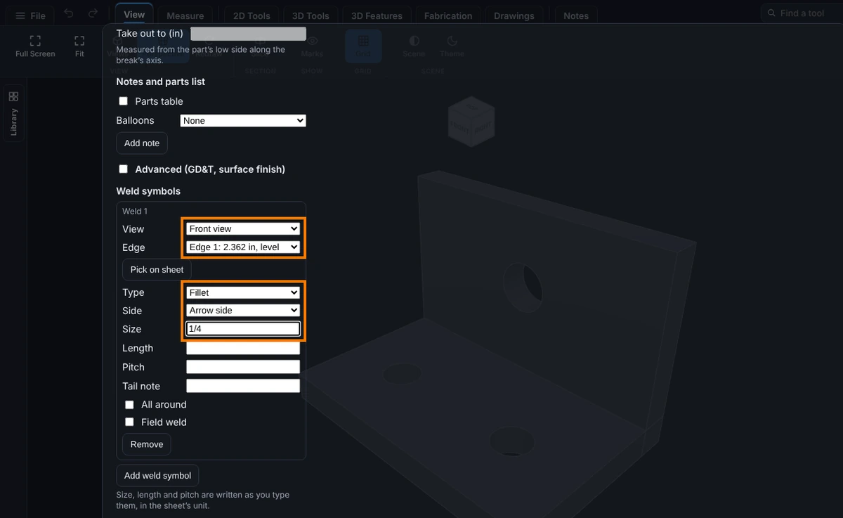
- At the bottom of the left side of the window, click Advanced options to open it, scroll to Weld symbols and click Add weld symbol. A box named Weld 1 appears. It starts on the longest edge of the front view, as a fillet weld on the arrow side (for the sample bracket: Front view, Edge 1: 2.362 in, level, Fillet, Arrow side).
- Pick the View: Front view, Top view, Right view or Isometric view.
- Pick the edge. Choose it in the Edge list, or click Pick on sheet and then click a line of the view on the preview. The arrow points at the middle of that edge.
- Pick the Type and the Side, and type the Size, Length, Pitch and Tail note the weld needs. Tick All around or Field weld when they apply.
- Check the preview. The line under it counts the weld symbols. When one cannot be drawn, the line says why and Download DXF is greyed out.
- Click Download DXF or Save as PDF at the bottom of the window.
Options
- Add weld symbol: adds a weld symbol at the end of the list. It is greyed out when there are 20.
- View: the view the arrow points into. It starts on Front view. Picking another view picks that view's longest edge. The isometric view needs Add an isometric view ticked.
- Edge: the view's visible lines, longest first, each with its length and its direction (for example Edge 1: 100 mm, level). At most 60 are listed. An edge picked on the sheet that is not among them is added at the top of the list.
- Pick on sheet: click it, then click a line of the front, top, right or isometric view on the preview. The nearest line within about one and a half letter heights of the click is picked. Click Pick on sheet again to stop without picking.
- Type: Fillet (a right triangle, its upright side on the left), Groove (V) (a V with its point on the line), Plug or slot (a box on the line) or Spot (a circle on the line). It starts on Fillet.
- Side: Arrow side puts the symbol below the line: the weld goes on the side of the joint the arrow touches. Other side puts it above the line: the weld goes on the far side. Both sides puts it on both. It starts on Arrow side. Plug and spot welds are one side only.
- Size: written left of the symbol: the leg of a fillet weld, the depth of a groove weld, the diameter of a plug or spot weld. Leave it empty to leave it off.
- Length: written right of the symbol: the length of each weld. Fillet and groove welds only. Leave it empty for a weld along the whole edge.
- Pitch: the distance from the middle of one weld to the middle of the next, for welds with gaps between them. On a fillet or groove weld it is written after the length (50-150) and must be more than the length. On a plug or spot weld it is written right of the symbol.
- Size, length and pitch each take a number more than 0 and at most 10,000: a whole number or a decimal (6, 0.25 or .5), a fraction (1/4) or a whole number and a fraction (1-1/2 or 1 1/2, written 1-1/2). Each holds at most 12 letters. They are written on the sheet as you type them, in the sheet's unit: millimeters on A4 and A3, inches on Letter and Tabloid.
- Tail note: words written after a fork at the far end of the line, such as the welding process (GMAW) or a specification. At most 40 letters (an emoji counts as one). Leave it empty for no tail.
- All around: a circle where the arrow meets the line. The weld goes all the way round the joint.
- Field weld: a filled flag where the arrow meets the line. The weld is made on site, not in the shop.
- Remove: takes that weld symbol away. The ones after it move up a number.
- Save as PDF: writes the sheet as a PDF file, drawn with the weld symbols as the preview shows them. It needs the same plan and share permission as Download DXF.
Where They Go
- Each symbol is placed outside its view, on the line from the middle of the view through the middle of the edge, turning 5 degrees at a time and then further out, until it is clear of every view, the title block, the parts table, the notes, the balloons and the other weld symbols, inside the border.
- A place where the arrow meets the edge at a slant of 15 degrees or more is taken first, so the arrow does not run along the edge when there is room.
- The arrow joins the end of the reference line nearer the edge, and the tail is at the other end. Size, length and pitch read left to right whichever end the arrow is on.
- In the DXF the symbols are on the WELD layer: lines, circles (all around and spot welds), the field weld flag as a filled shape, and the text. The layer is added only when the sheet has a weld symbol.
- The weld symbols stay with the model while the page is open: close the window and open it again and they are back. Opening another model or reloading the page starts with none.
Limits
- At most 20 weld symbols on a sheet, 40 letters in a tail note and 12 letters in a size, length or pitch.
- Four weld types: fillet, V groove, plug or slot, and spot. No square, bevel, U or J groove, seam, stud, surfacing, backing or melt through symbols, no contour or finish marks, no groove angle or root opening, and no count of welds in brackets yet.
- A Both sides weld has one size, length and pitch for both sides.
- A symbol points at the middle of a whole line of a view. A round edge is drawn as many short lines, so it is picked one short line at a time. Section, detail and auxiliary views cannot take a weld symbol.
- Symbols are placed for you. You cannot drag them yet; to move one, pick an edge in another view, change the scale or pick a bigger sheet. An arrow can cross a line of a view or another arrow.
- The weld symbols are not saved in the model file. Download the DXF or print the sheet to keep them.
- Placing the weld symbols takes at most 2 seconds. Past that the window says so.
Common Mistakes and Messages
- "Weld 1 has no edge. Pick one in its Edge list, or click Pick on sheet and then a line of the view." Pick one in its Edge list, or click Pick on sheet and then a line of the view.
- "The edge of Weld 1 is not in the front view now (the views changed). Pick its edge again." A break or another choice changed the lines of the view. Pick its edge again.
- "Weld 1 is on the isometric view, which is not on the sheet. Tick Add an isometric view, or pick another view for the weld." Tick Add an isometric view, or pick another view for the weld.
- "Weld 1: a spot weld is shown on one side only. Pick Arrow side or Other side." Pick Arrow side or Other side. A plug weld says the same.
- "Weld 1: “1,5” in Size is not a size. Type a number more than 0 and at most 10,000, such as 6, 0.25 or 1/4." Type a number more than 0 and at most 10,000, such as 6, 0.25 or 1/4. Length and Pitch say the same.
- "Weld 1: Length is for fillet and groove welds. Clear it; a plug or spot weld uses Pitch for its spacing." Clear Length; a plug or spot weld uses Pitch for its spacing.
- "Weld 1: a pitch needs a length (the length of each weld, then the pitch from the middle of one to the next). Type a Length, or clear Pitch." Type a Length, or clear Pitch.
- "Weld 1: the pitch (2) must be more than the length (2), or the welds run into each other. Make the pitch bigger, or clear it for one weld." Make the pitch bigger, or clear it for one long weld.
- "Weld 1: the tail note is 41 letters long. A tail note holds at most 40; shorten it." Shorten it.
- "Weld 1: the tail note has a hidden or control character in it" Text pasted from elsewhere can hold an invisible character (a direction mark, a zero width space, a soft hyphen or a line break). Clear the box and type it again. Size, Length and Pitch say the same.
- "Weld 1 finds no free place on the sheet clear of the views." Pick a smaller scale or a bigger sheet, shorten its tail note, or pick an edge in another view.
- "There are 21 weld symbols. A sheet holds at most 20" Remove some.
- "There is no line of the front, top, right or isometric view there." Click closer to a line of a view.
- "Placing the weld symbols took longer than 2 seconds" Remove some weld symbols, or pick a bigger sheet.
- The printed sheet is the wrong size: in the print window pick the sheet's paper size and a scale of 100 (not fit to page).
Tips
- Pick the edge in the view where the joint is seen edge on: the line where the two parts meet.
- For welds on both sides of a T joint, use one symbol with Both sides rather than two symbols.
- Put the shop's welding process or a specification in the tail note, such as GMAW or AWS D1.1.
- On a busy sheet, a bigger sheet gives the symbols room close to their edges.