Make Drawing (Views, Sections and Center Marks)
Puts the part on a drawing sheet: a border, a title block you fill in, and the three standard views (front, top and right) at the scale you choose. You can add an isometric view and a section view, and round holes get center marks. A detail view, an auxiliary view and a broken view have their own page: Detail, Auxiliary and Broken Views. Download it as a DXF file for your CAD program or the shop, or save it as a PDF to print or send. A left, bottom or back view, and saving as PDF, have their own page: Save as PDF and Projected View.
What you get: a drawing sheet with the front, top and right views of your part at the scale you pick, a filled in title block and center marks on round holes, downloaded as a DXF file named after the model (sample-bracket-drawing.dxf for the sample bracket) that opens at full size in your CAD program.
Sheet sizes and one sheet per part: the Sheet list has A4, A3, Letter and Tabloid, and the large US sheets ANSI C (22 x 17 in), ANSI D (34 x 22 in), ANSI E (44 x 34 in) and the architectural sheets ARCH C (24 x 18 in), ARCH D (36 x 24 in, the 24 x 36 sheet turned on its side), ARCH E1 (42 x 30 in) and ARCH E (48 x 36 in). The PDF page is exactly the sheet, so it plots at full size. When more than one part is shown, One sheet per part appears under the hidden lines box. Tick it and Download DXF or Save as PDF makes one sheet for each part (the three views, and the isometric view if ticked, at each part's own scale, with the part's name in the title block) and saves them together in one zip file. Parts of the same shape (a pair of gussets, a row of bolts) get one sheet that says how many are needed, such as (2 REQUIRED) after the name. Notes, balloons, section, detail and the other extra views stay on the one sheet drawing; untick the box to put them on.
Step by Step
- Open a 3D part. Show the bodies you want on the drawing and hide the rest: only the bodies shown are drawn.
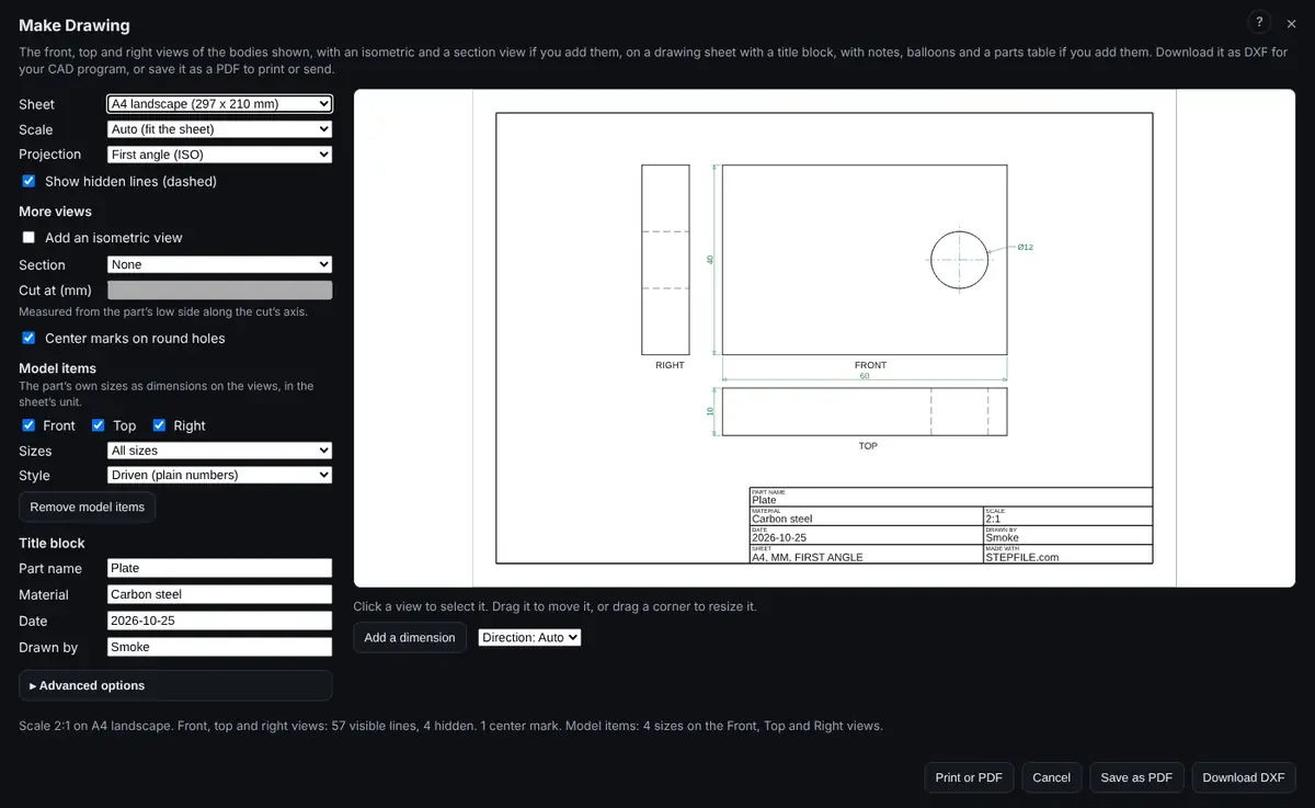
- Once the model has finished loading, click the Documents tab, then Make Drawing (or open File, then New, then Drawing of This Part...). The Make Drawing window opens. It works out the views (a second or so on a big part) and shows the sheet on the right, with a line under the settings that counts the lines, such as Scale 1:1 on Letter landscape. Front, top and right views: 119 visible lines, 10 hidden. 3 center marks.
- Pick the Sheet, the Scale and the Projection, and tick or untick Show hidden lines (dashed). The picture follows each choice.
- Under More views, tick Add an isometric view if you want one (and Pull the parts apart in the isometric view to show an assembly exploded: each part slides out along the axis it lies furthest out on, and the view is named EXPLODED ISOMETRIC, with a dashed line from where each part was to where it is now; the balloons keep clear of the name), pick a Section (a cut along X, Y or Z) and type where it cuts in Cut at, and tick or untick Center marks on round holes. The views are worked out again after each of these choices.
- Fill in the Title block: Part name, Material, Date, Drawn by, Drawing no. (starts as the model's name in capitals with hyphens, such as UNIVERSAL-TUBE-CLAMP; type over it, and with one sheet per part each part's sheet adds -01, -02 and so on), Revision (starts at A), Weight (worked out from the material, and you can type over it) and Tolerance (a general tolerance note, in the sheet's unit). Checked by, Approved by, Revision note and General notes (one note to a line; the window starts with four standard ones, the tolerance note saying how many places each size is held to, and you can edit or clear them; the Weld note box adds one more note, on the assembly sheet only, such as WELD ALL TAB AND SLOT JOINTS, 1/8 FILLET BOTH SIDES; weld symbols are placed by hand with Add weld symbol, or by the AI with welds, because only you know which joints are welded; the AI names each joint with a point near it or a number from weld_edges, never a guess) fill the strip left of the title block: a box of numbered general notes, a box with the revision, who checked it and who approved it, and the projection symbol for the angle you picked (the cone seen from the side on the left and from the end on the right for third angle, the other way round for first angle). An empty box leaves its part off. The sheet also says which sheet it is, such as 2 OF 8 when one sheet per part is saved. With the parts table on, the zip starts with the assembly sheet as 1 OF 8 and the parts follow as 2 OF 8 to 8 OF 8, so the set counts as one. Everything else (projected, detail, auxiliary and broken views, the parts table, balloons, notes, GD&T and weld symbols) is under Advanced options, closed at first.
- Click Download DXF at the bottom of the window. The file downloads, named after the model and ending in -drawing.dxf. A message gives the sheet, the scale, the number of lines and the unit, for example "Drawing saved as DXF: Letter landscape, scale 1:1, 147 lines, in inches." Or click Save as PDF for a PDF of the same sheet (see Save as PDF and Projected View).
Options
- Sheet: A4 landscape (297 x 210 mm), A3 landscape (420 x 297 mm), Letter landscape (11 x 8.5 in) or Tabloid landscape (17 x 11 in). A4 and A3 sheets are written in millimeters, Letter and Tabloid in inches, and the file says which.
- Scale: Auto (fit the sheet) takes the largest scale from the list that fits all the views on the sheet (the three views, and the isometric and section views when you add them). Or pick one: 10:1, 5:1, 4:1, 2:1, 1:1, 1:2, 1:4, 1:5, 1:10, 1:20, 1:50 or 1:100. 1:2 means the part is drawn half size.
- Projection: Third angle (US) puts the top view above the front view and the right view to its right. First angle (ISO) puts the top view below the front view and the right view to its left. It starts on third angle when your display unit is inches or feet, and on first angle otherwise. The title block says which one the sheet uses.
- Show hidden lines (dashed): edges behind the part are drawn as dashed lines on their own layer. Untick it to leave them out. It starts ticked.
- Add an isometric view: adds the part seen from the corner between the front, top and right (the viewer's own ISO view), right of the three views. It starts unticked.
- Section: None, Cut along X (seen from the right), Cut along Y (seen from the top) or Cut along Z (seen from the front). It starts on None. See Section View below.
- Cut at: where the section cuts, as a distance from the part's low side along the cut's axis, in millimeters (mm) or, when your display unit is inches or feet, in inches (in). You can also type the unit after the number (12 mm, 2 cm, 0.5 in), and it wins over the unit beside the box. When you pick a cut it fills in half way along the part. It must be more than 0 and less than the part's size along that axis, and at most 24 letters long.
- Center marks on round holes: a cross through the center of each round hole, in each view that looks straight down the hole. It starts ticked.
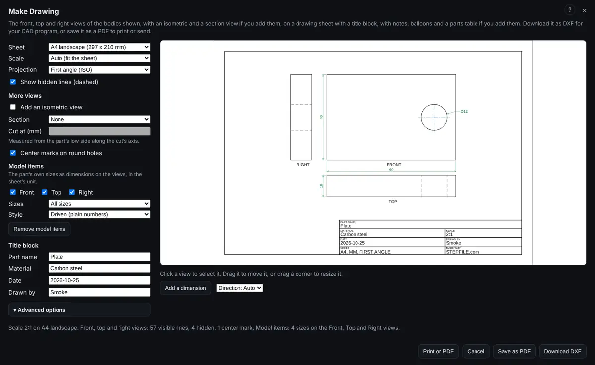
- Advanced options: the choices fewer drawings need: projected, detail, auxiliary and broken views, parts table, balloons, notes, GD&T and weld symbols. The button at the bottom of the left side opens or closes them, and your choice is remembered in this browser. It stays open, and cannot be closed, while the drawing holds any of them, so nothing on the sheet is ever hidden.
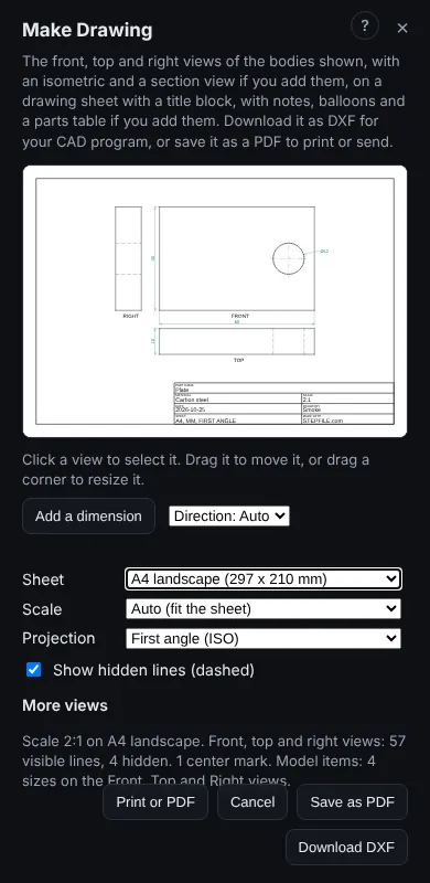
- The whole page: the window fills the page, with the options on the left and the sheet beside them. On a narrow screen (a phone) the sheet is on top, stays in view while you scroll the options below it, and the buttons stay at the bottom.
- Advanced (GD&T, surface finish): a box that shows or hides the Surface finish and tolerance frames section (the Surface Finish and GD&T page, listed below, says how to use it). It starts unticked, is remembered in this browser, and stays ticked while the drawing holds a symbol or a frame. Weld symbols, notes, the parts table, balloons and model items are always shown.
- Title block: Part name (it starts on the model's name), Material (the part's material), Date (today) and Drawn by (your account name). Each holds at most 60 letters (an emoji counts as one). The Scale box of the title block is filled in for you.
Section View
- Pick a Section. A cut along X is a flat cut square to X; the part right of the cut is taken away and what is left is seen from the right, like the Right view. A cut along Y takes away the part above the cut and looks from the top. A cut along Z takes away the part in front of the cut and looks from the front.
- Type the place in Cut at, from the part's low side (its left end for X, its bottom for Y, its back for Z).
- The view is labelled SECTION A-A and sits right of the three views (under the isometric view when there is one, or beside it when that fits the sheet better). The cut face is hatched with lines at 45 degrees. Edges behind the cut that you can see are drawn; hidden ones are left out.
- A cutting line, marked A at both ends, shows where the cut is: on the Front view for a cut along X or Y, on the Top view for a cut along Z. The arrows at its ends point the way the section view looks.
- Where bodies overlap, the cut face is hatched as one piece; a hollow inside a body is left open.
Center Marks
- A round hole gets a cross through its center, reaching a little past the hole's edge, drawn in long and short dashes (layer CENTER, line type CENTER).
- It shows in the views that look straight down the hole: a hole along Z in the Front view, along Y in the Top view, along X in the Right view, and in the section view when the cut is along the hole and the hole reaches the part that is left.
- A hole counts when its face goes all the way round and faces its own axis (the inside of a hole), and the axis runs along X, Y or Z. Holes on one center (a counterbore) get one cross, as wide as the biggest.
What Is in the Drawing
- The views are the viewer's own Front, Top and Right views, so the drawing looks like the part does when you click those views.
- Lines are the part's edges: where two faces meet, plus the outline of round faces seen from the side (the two sides of a cylinder lying down).
- An edge hidden behind the part is dashed (layer HIDDEN, line type HIDDEN). Where a hidden edge lies under a visible one, only the visible one is drawn.
- Layers: VISIBLE (the part's lines), HIDDEN (dashed), BORDER (the border and the title block lines), TITLE (the title block text) and NOTES (the FRONT, TOP and RIGHT labels, and the ISOMETRIC, SECTION A-A and A labels). The paper's edge is a rectangle on layer 0. When the sheet has them, CENTER (center marks), HATCH (the section's hatching) and CUT (the cutting line) are added, with the CENTER line type of long and short dashes.
- The drawing is at full sheet size: open it in your CAD program and print it at 1:1 on the sheet you picked.
Limits
- Sizes come from Model items and Add a dimension (see Make Drawing: Model Items); a broken view writes the part's true length (see Detail, Auxiliary and Broken Views). One left, bottom or back view can be added with Projected view, and Save as PDF saves the sheet as a PDF file (see Save as PDF and Projected View).
- One section view per sheet, a flat cut square to X, Y or Z only (no slanted or stepped cut, no half section), always seen from the high side of the cut (you cannot turn it to look the other way yet). The hatching is one pattern (45 degrees, 2.5 mm or 0.1 in apart on the sheet) for every material.
- The section needs a closed part. On a part with open edges (a surface, or a mesh with holes in it) the hatching can come out wrong.
- The isometric view has no hidden lines, and no center marks.
- Center marks need the faces of a STEP part: a mesh with no faces (an STL) gets none. Holes with a slanted axis, slots and part holes (less than all the way round) get none. At most 2,000 marks on one view.
- Hatching: at most 50,000 lines on one sheet.
- Landscape only, with one title block layout. One sheet per part saves one sheet for each part.
- The front view is always the viewer's Front view. You cannot pick another side as the front yet.
- Round edges are written as many short straight lines, not as arcs or circles. They print the same, but a CAD program sees lines.
- The lines come from the part's mesh, so the outline of a round face seen from the side can sit a little off its true place (at most about a thousandth of the part's size).
- Hidden or not is judged on a picture of the part about 1000 points across. On a very small detail of a large part, a short piece of an edge can come out visible when it is hidden, or the other way.
- At most 600,000 triangles (hide some bodies on a bigger model), 150,000 lines on one sheet, 8 seconds and 60 million steps to work out the views. Past any of these the window says so and nothing downloads.
- It needs the Advanced plan or higher, and on a shared model the Exports box ticked.
Common Mistakes and Messages
- Download DXF is greyed out. A choice cannot be drawn. The line under the settings says why in words; put that right and the button comes back.
- "The part does not fit on the ... sheet even at 1:100." Pick a bigger sheet.
- "At 10:1 the views need 39.92 x 32.05 in, and this sheet has 9.1 x 5.3 in for them. Pick a smaller scale, a bigger sheet or Auto." The scale is too big for the sheet. Pick a smaller scale, a bigger sheet, or Auto.
- "Part name is 61 letters long. A title block field holds at most 60; shorten it." A title block field holds at most 60 letters. Shorten it. Material, Date and Drawn by say the same.
- "This part has ... triangles, more than the 600,000 a drawing can read." Hide some bodies in the Model tree and open Make Drawing again.
- "Working out the views took longer than 8 seconds, so it was stopped. Hide some bodies, or open a simpler part, and try again." Hide some bodies, or open a simpler part, and try again.
- "Drawing this part needs more than 60 million steps (many faces lie over each other), so it was stopped." Many faces lie over each other (a stack of thin plates, a fine mesh). Hide some bodies, or open a simpler part, and try again.
- "3 triangles with numbers that are not real sizes were left out." The file has a few broken triangles. The rest of the part is drawn; check the views against the model.
- "Type where the cut goes.", "... is not a number." or "A cut at 500 in misses the part." Type a number in Cut at, more than 0 and less than the size the message gives, in the unit beside the box or with mm, cm or in after it.
- "The section's hatching would need more than 50,000 lines. Pick a smaller scale, or cut through a smaller part of it." Pick a smaller scale, or cut through a smaller part of it.
- "The cut leaves nothing of the part to draw." Move the cut.
- "No body is shown." Show a body in the Model tree first.
- "There is no solid yet, so there is nothing to draw." A part drawn here has only sketches so far. Extrude something first.
- "This file is a 2D drawing already." A DXF, SVG or PDF is flat already; Make Drawing works on a 3D part.
- "Make a drawing and save it as DXF on the Advanced plan or higher." The plan does not include exports.
- "The owner of this model has not allowed exports." The share does not have the Exports box ticked.
- The drawing prints at the wrong size: print it at 1:1 (no fit to page), on the sheet you picked.
Tips
- Look at the part from the Front, Top and Right views first (see Views): that is what the three views of the drawing show.
- Untick hidden lines on a busy part: the views get much easier to read.
- A section through the middle of a hole shows its inside: for a hole along Z, pick a cut along X (or Y) and type the place of the hole's center.
- The extra views take room on the sheet: with an isometric and a section view, Auto may pick a smaller scale, or pick a bigger sheet.
- Pick a sheet in your own unit (Letter or Tabloid for inches, A4 or A3 for millimeters) so the file opens at the size you expect.
Related Pages
- Make Drawing: Detail, Auxiliary and Broken Views
- Make Drawing: Save as PDF and Projected View
- Drawing Notes, Balloons and Parts Table
- Exporting Parts, Faces and Files
- Drawing Weld Symbols
- Export This Face as DXF
- Export as IGES, for exact surfaces
- Export This Part as STL
- Drawing Surface Finish and GD&T Symbols
- Make Drawing: Model Items
A drawing with one sheet per part numbers each sheet from the body's name: the drawing number follows the body name, so a body called Base plate on drawing UNIVERSAL-TUBE-CLAMP gets UNIVERSAL-TUBE-CLAMP-BASE-PLATE, and a body still called Body 7 gets -07. In the parts table and on the part's own sheet a body still called Body 7 is shown by its shape and size instead, such as PLATE 1/4 X 4 X 6, BAR 2 X 2 X 36 or BLOCK 3 X 4 X 5 on its own sheet (the parts table says PLATE 1, BAR 2 and so on, with the size in the Stock column). A long hollow square or rectangle reads TUBE 2 X 2 X 1/8 X 36 and an L section reads ANGLE 2 X 2 X 1/4 X 24, with the wall worked out from the cut outline. A welded frame of tube or bar reads FRAME 2 X 18 X 24 (its box), not a plate. A balloon pointing at a part other parts cover lands on the part itself, never in the empty middle of a frame. Rename a body in the parts list (double-click, with the 2D Tools or 3D Features tab open) before making the drawings. The AI does the same with model.rename_body. Two bodies with the same name, or a name with no letters, take their sheet position instead.