Make Drawing: Model Items
Model items in the Make Drawing window puts the part's own sizes on the drawing for you: the overall width, height and depth, the length of each straight edge, the diameter of each hole or round edge and the radius of each rounded corner, drawn as proper dimension lines with arrows and numbers in the sheet's unit.
What you get: green dimension lines on the Front, Top and Right views (the ones you tick), each size written once, kept clear of the views, notes, balloons, weld symbols and tolerance frames, and saved in the DXF, the PDF and the print like the rest of the sheet.
Step by Step
- Open a 3D part. Click the Drawings tab, then Make Drawing (or open File, then New, then Drawing of This Part...). The Make Drawing window opens with the front, top and right views on a sheet (see Make Drawing).
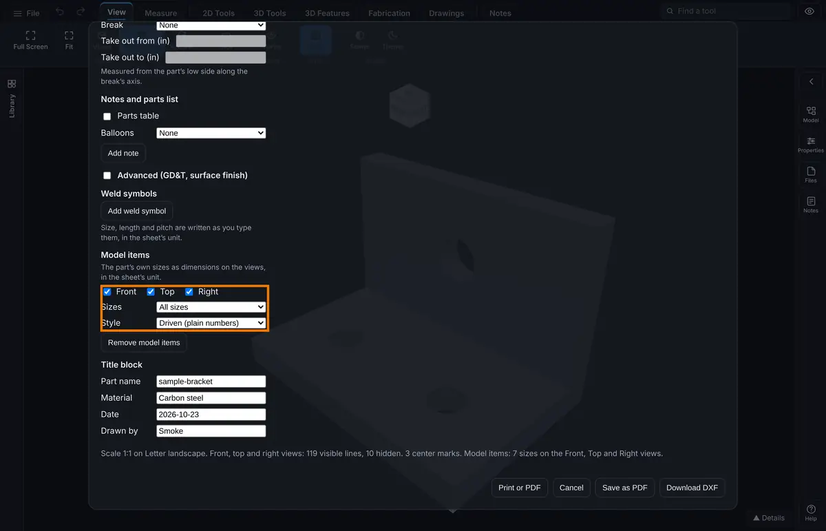
- On the left of the window, find Model items (under More views, above Title block). Front, Top and Right are ticked, Sizes says All sizes and locations and Style says Driven (plain numbers). Model items is already on, so the sizes are on the sheet when the window opens.
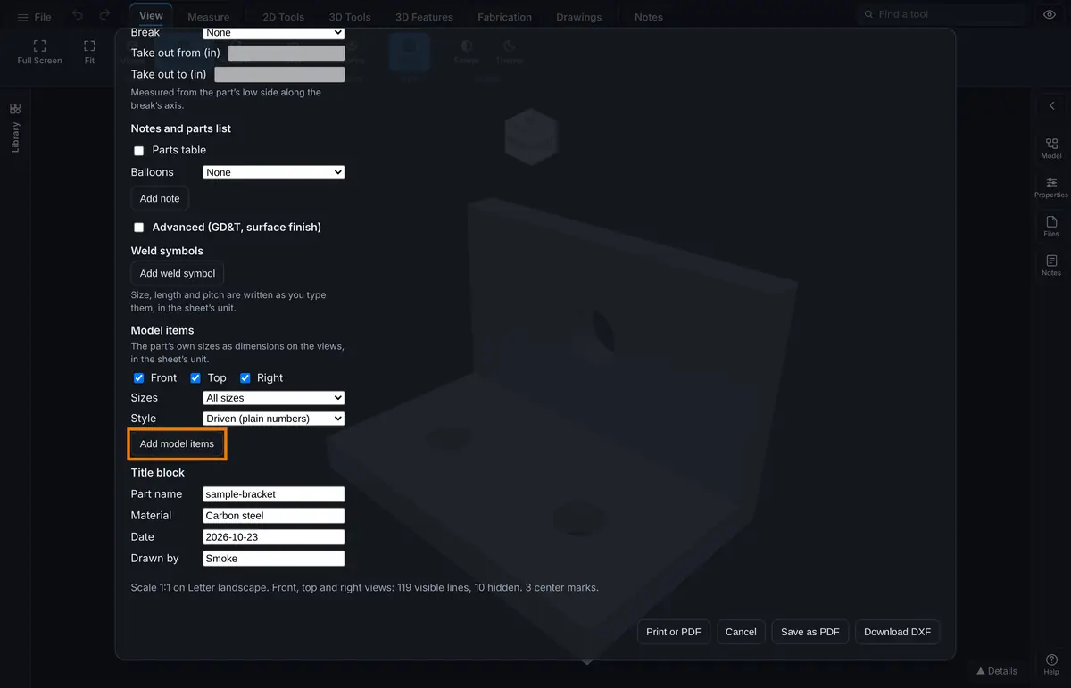
- Look at the picture. The sizes show in green on the views, and the button reads Remove model items. If you took them off, click Add model items to put them back.
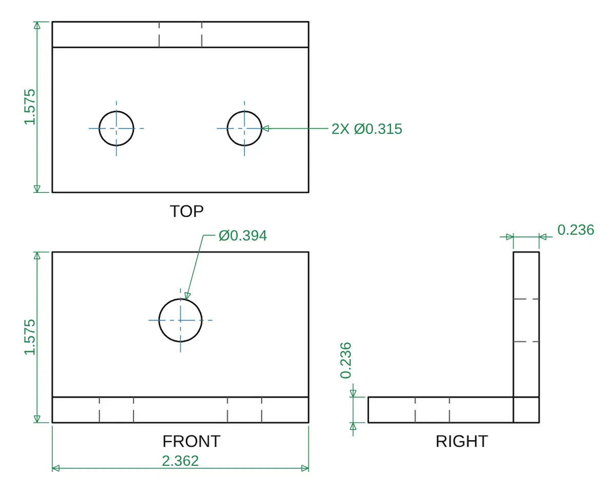
- Check the line under the settings. It counts the sizes and names the views, for example: Model items: 7 sizes on the Front, Top and Right views. If a size found no free place on the sheet, it says how many were left out. With Scale set to Auto (fit the sheet), Auto scale picks the biggest scale that still leaves room for the sizes, and the line says which one it picked. With One sheet per part ticked, each part's sheet gets all of its own sizes and where each hole and slot sits, even when the window is set to Overall sizes only for the assembly sheet.
- To change what is shown, untick a view (Front, Top or Right), set Sizes to Overall sizes only for just the width, height and depth, or set Style to Reference (in brackets). The picture changes straight away.
- Click Download DXF or Save as PDF at the bottom of the window. The sizes are saved with the sheet, on a layer of their own named MODELDIM in the DXF.
- To take the sizes off again, click Remove model items.
Options
- Front, Top, Right: the views that get sizes. All three are ticked at first.
- Sizes: All sizes: the overall width (X), height (Y) and depth (Z), every level or upright straight edge, every hole or round edge seen as a whole circle (a diameter, such as Ø16, or 2X Ø8 when one view has two the same) and every rounded corner (a radius, such as R10, or 4X R10 when one view has four the same). A straight edge that runs into a rounded corner is measured to the sharp corner, where the two edges would meet without the rounding, the way a drafter sizes it: a 70 long top edge with an R10 at its end is written 80.
- Sizes: All sizes and locations: all of the above, and where each hole, slot end and edge inside the part sits. Each place gets a thin line out past the view with its distance from the view's lower left corner written at the end, in rows so the numbers never touch (a drafter's ordinate sizes). A place that matches a number already written is not written twice. At most 16 across each side of a view. The holes a diameter note names are then located one by one, which is what a shop needs to cut the part. A hole that runs right through the part says THRU after its diameter, and when its diameter is the clearance for a common bolt it names the bolt, such as 2X Ø0.4 THRU (3/8 BOLT), so the shop knows what it is for; a hole that stops inside the part, or has a step in it, gets neither. A hole of the size a thread is drilled for says so, such as Ø0.313 THRU (3/8-16 TAP DRILL): it is the drill size, not a check that the thread is cut. A place is never written twice: a size from the corner of the view to a place is that place, and a size between two places leaves out the farther one.
- Sizes: Overall sizes only: just the overall width, height and depth.
- Style: Driven (plain numbers): the size as a number, such as 100.
- Style: Reference (in brackets): the size in brackets, such as (100), the way a drawing marks a size given for information only. Both styles are plain notes on the sheet: changing one does not change the part.
How the Sizes Are Placed
- The width goes on the Front view (or the Top view when Front is unticked), the height on the Front view (or the Right view), the depth on the Top view (or the Right view).
- A size is written once. A straight size along X, Y or Z that is already on the sheet is not written again on another view.
- Each dimension line goes outside its view, on the side nearer its edge first, one letter height further out at each try, then on the other side. Smaller sizes go nearer the view and bigger ones further out.
- A diameter or radius gets a leader with an arrow on the circle, pointing at its center, and a short level line to its number. The leader takes the way out of the view across the fewest of its lines (so it goes between the other holes where it can), and of those the shortest.
- Nothing is put over the views' labels, the title block, the parts table, the notes, balloons, weld symbols, surface finish symbols or tolerance frames (also those inside a view) or their leaders. No dimension line or leader crosses another size's lines, and no extension line crosses a dimension line or a leader. Extension lines may cross each other, as on any drawing. A size that finds no free place is left out and counted.
Limits
- Only the Front, Top and Right views get sizes. The isometric, section, detail, auxiliary and projected views get none.
- A sloped edge gets no size, because its length in a view is only true when the view looks straight at it. Use a note for it.
- A round edge needs at least 5 short lines on the sheet (a very small or coarse circle may be read as straight lines).
- At most 24 sizes on a view and 60 on a sheet; the rest are left out and counted. A view of more than 50,000 lines is not read (pick Overall sizes only).
- Model items and a broken view cannot be on one sheet yet.
- Placing the sizes stops after 2 seconds.
- Sizes are in millimeters to 2 places on A4 and A3 sheets, and in inches to 3 places on Letter and Tabloid sheets.
Common Mistakes and Messages
- "Model items is on, but no view is ticked for it. Tick Front, Top or Right, or click Remove model items." Tick at least one of Front, Top or Right.
- "Model items and a broken view cannot be on one sheet yet. Set Break to None, or click Remove model items." Set Break back to None, or take the sizes off.
- "None of the model items finds a free place on the sheet clear of the views, notes and symbols. Pick a smaller scale or a bigger sheet." The views fill the sheet. Set Scale to a smaller scale or Auto (fit the sheet), or pick a bigger Sheet.
- "... left out: no free place clear of the views, notes and symbols" under the picture. Some sizes did not fit. Pick a smaller scale or a bigger sheet, or move a note or symbol to another view.
- "Placing the model items took longer than 2 seconds, so it was stopped." Pick Overall sizes only, or untick some views.
- "The Front view has ... lines, more than the 50,000 Model items reads." Pick Overall sizes only, or untick that view.
- A hole has no diameter. It is dashed in that view (hidden), or it is not round in that view. Look at the view that looks straight down the hole.
- A size I need is missing. It may be a sloped edge, the same size as one already written, or on a view you did not tick. Add it as a note.
- An edge is longer than I measured. An edge that runs into a rounded corner is measured to the sharp corner, not to where the rounding starts. Add the shorter size as a note if you need it.
Tips
- Add the sizes last, after the notes, balloons and symbols, and look over the picture: a busy sheet may need a bigger sheet or a smaller scale.
- Use Overall sizes only for a quick cutting size, All sizes for a drawing that gives the sizes, and All sizes and locations for a shop drawing a part is cut from.
- Pick Reference (in brackets) when the drawing is for information and the 3D part is the master.