Direction 2
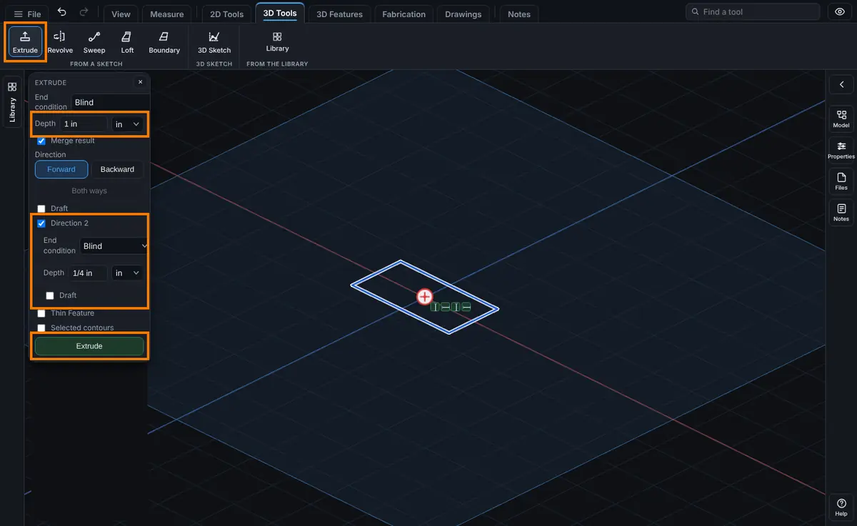
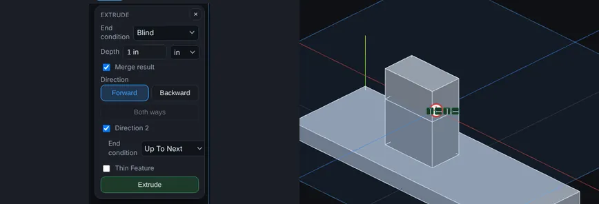
An option for Extrude and Cut. It adds a second direction, opposite to the first, with its own end condition. The two directions are made as one feature. You can run one side 1 in and the other side up to the next face, all in a single step. For a guided example with pictures, see the Direction 2 Walkthrough.
What you get: one Extrude or Cut step that runs one way from the sketch with its own end, and the opposite way with a second end of its own.
When to Use It
- Extrude a profile 1 in one way and 1/4 in the other way
- Grow a boss from the sketch plane up to one plate and down to another plate in one step
- Cut through a part on one side of the sketch and only part way on the other side
- Make one feature where Both ways would be the wrong shape, because the two sides are not equal
How It Works
Direction 1 is the Direction you already choose: Forward or Backward. Direction 2 is always the opposite way. Each direction has its own End condition:
- Blind: a depth of its own
- Through All (Cut only): all the way through the part
- Up To Next: stops on the first face it meets
- Up To Surface: stops on a face you click, with an optional offset
The two halves are joined into one tool, and the tool is added or cut in one step, so the Model tree shows one step and one Undo takes it back.
Step by Step
- Open a sketch on a plane or a face and draw a closed profile (see Planes and Faces). Sketching is part of modeling, which comes with the Pro plans.
- Click Extrude (or Cut) on the Features tab.
- Set Direction 1 as usual: type a Depth or choose another End condition, and choose Forward or Backward.
- Tick Direction 2. A block with its own End condition opens under it, and Both ways is greyed out.
- In the Direction 2 End condition, choose Blind and type a Depth such as
1/4 in, or choose one of the other end conditions. - For Up To Surface, click the face on the part. It lights up in blue. Type an Offset Distance if you want to stop short of it, and tick Reverse offset to run past it.
- Click Extrude (or Cut). The feature goes both ways at once.
- The Model tree shows one step, named for what it did, for example Extrude rectangle, 1 in, direction 2 1/4 in for the Blind 1/4 in above, or Extrude rectangle, 1 in, direction 2 up to next.
Options
- Direction 2 (tick box): turns the second direction on. Off is the plain feature.
- End condition (for Direction 2): Blind, Through All (Cut only), Up To Next or Up To Surface.
- Depth (Blind): how far Direction 2 goes. It takes units and formulas, like the main Depth box.
- Face (Up To Surface): the face Direction 2 ends on. Click the Face button again to choose another.
- Offset Distance and Reverse offset (Up To Surface): stop short of the face, or run past it.
Direction 2 and Both ways cannot be used together. Both ways splits one depth evenly; Direction 2 gives each side its own end. Tick Direction 2 and Both ways switches off. To get an even split with Direction 2, give both directions the same Blind depth.
Edit It Later
Right-click the step in the Model tree and choose Edit Feature. The Direction 2 tick box, its End condition, Depth, face and offset are all there. Press Esc or the X to close without changing anything.
Tips and What to Expect
- If Direction 2 has no face to stop at, the step is refused with a message that starts with Direction 2: and says why. Nothing is added.
- Direction 1 and Direction 2 are measured from the same sketch plane, one each side.
- Direction 2 works with Thin Feature (see Thin Feature) and with Flip side to cut (see Flip side to cut).
- A Pattern can repeat a step whose Direction 2 ends Up To Next or Up To Surface. Every copy finds its own end, as in Up To Next.
- An older version of the viewer (6.333.0 or earlier) opens the model with Direction 1 only. The shape it builds is simpler, because Direction 2 is left out. The file is not damaged, and opening it again here brings Direction 2 back.
Common Mistakes and Messages
- "Set a positive depth for Direction 2, or choose another End condition." Direction 2 is Blind and its Depth box is empty or 0. Type a depth such as
1/4 in, or choose Up To Next or Up To Surface. - Both ways is grey. Direction 2 is ticked, and the two cannot be used together. Untick Direction 2 to use Both ways, or give both directions the same Blind depth.
- A message that starts with "Direction 2:" The second direction found nothing to stop at, for example Up To Next with no face behind the sketch. Choose Blind for Direction 2, or move the sketch.
- The feature went the wrong way. Direction 1 follows Forward or Backward, and Direction 2 always runs the other way. Swap Forward and Backward, then swap the two depths.