Direction 2 Walkthrough
A step by step example of Direction 2: a block that grows 1 in up from the sketch and runs down to the first face below it, in one step. For everything the option can do, see Direction 2.
Before You Start
- Modeling comes with the Pro plans.
- The examples use inches. Use any unit you like, and type it after the number.
Make a Plate
- Open a sketch on the Top plane and draw a rectangle 4 in by 3 in with the Center Rectangle tool.
- On the Features tab, click Extrude, set Depth to
1/2 inand click Extrude. This is the plate.
Grow a Block Both Ways
- Click Sketch. In the Sketch on panel, type
2 inin the Offset box, then click Top (see Reference Planes). The sketch opens on a plane 2 in above the plate. Draw a rectangle 2 in by 1 in over the plate. - Click Extrude. Leave End condition on Blind and set Depth to
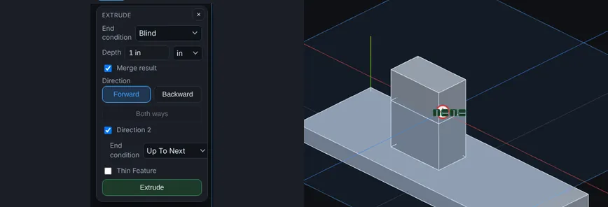
1 in. Leave Direction on Forward. - Tick Direction 2. A second End condition appears, and Both ways is greyed out.
- In the Direction 2 End condition, choose Up To Next. It has no depth box, because the part decides.
- Click Extrude. The block grows 1 in up from the sketch, and down it runs until it lands on the top of the plate.
- The Model tree shows one step: Extrude rectangle, 1 in, direction 2 up to next.
Change the Second Side
- Right-click the step in the Model tree and choose Edit Feature.
- Under Direction 2, change End condition to Blind and type
1/4 inin its Depth box. - Press Enter. The block now stops 1/4 in below the sketch, and a gap shows over the plate.
- The step reads Extrude rectangle, 1 in, direction 2 1/4 in.
Tips
- Direction 1 is Forward, so Direction 2 goes Backward. Choose Backward for Direction 1 and the two swap.
- To stop short of a face, use Up To Surface for Direction 2 and type an Offset Distance.
- Press Esc, or click the X, to close the Edit Feature editor without a change.