Hinge Mate
A Concentric plus a Coincident in one step. It leaves one turn free, like a door on its pin.
What you get: the two components sharing one center line with the two flat faces touching, free to swing about that line only, and one mate named Hinge1 in the Mates folder (not a Concentric and a Coincident).
When to Use It
- Hang a door or a lid
- Join two links on a pivot pin
- Make a swing arm
Step by Step
- Open an assembly (assemblies need the Pro plan) with at least two components in it. See Assemblies: Start and Insert Parts.
- Click Mate on the Assembly tab (or right-click a component and choose Assembly tools, Mate...), then click the Mechanical tab at the top of the window.
- Click a round face, circular edge or axis on the first component. It shows as the first Concentric pick.
- Click the matching round face, circular edge or axis on the second component. They must share a center line.
- Click a flat face on the first component, then a flat face on the second. They show as Coincident picks and are the faces that touch.
- Click Hinge. It is lit after the fourth pick. (After only the two round picks, Gear is the one lit: two round faces can be a Gear, never a Hinge.)
- Click the green check. The message reads "Hinge1 added."
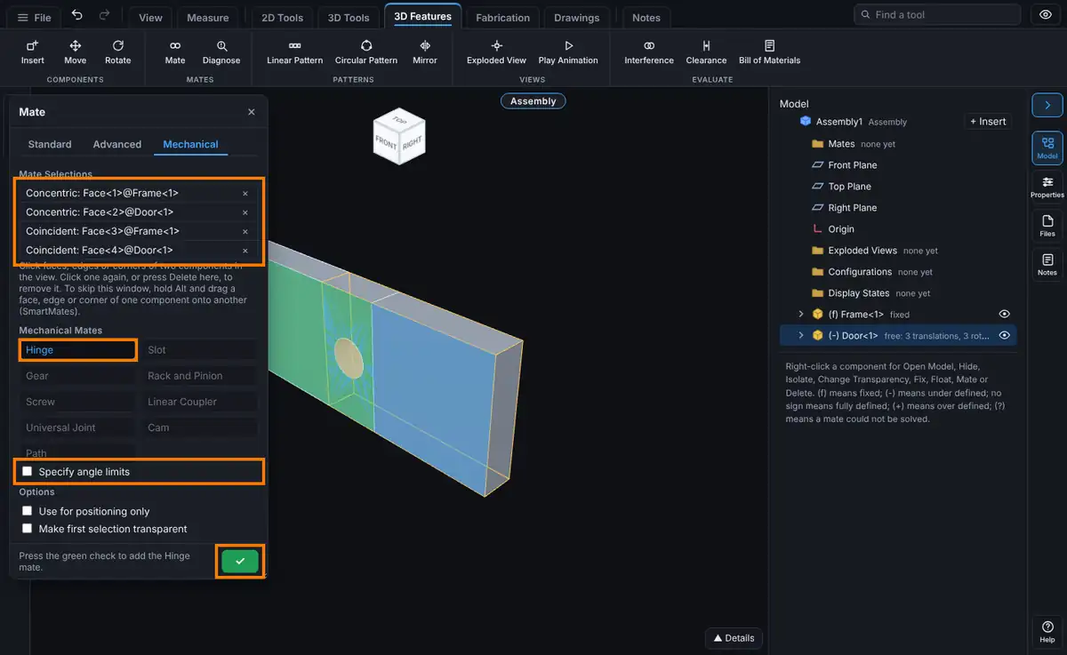
To limit the swing, tick Specify angle limits first. The hinge then takes six picks: after the two flat faces, pick two Angle selection entities, one on each component (two flat faces, or two axes). Then set Maximum and Minimum (degrees) and an Angle (degrees) to start from, and add the mate.
Options
- Specify angle limits: adds two picks and the Maximum, Minimum and Angle boxes. Maximum starts at 180 and Minimum at 0.
- If you type an Angle, the parts are first turned to it (kept inside the limits), then the hinge is added.
- Use for positioning only and Make first selection transparent work as on the Standard tab.
Tips and What to Expect
- The two components must be different. The window says "A hinge joins two different components." otherwise.
- Pick one flat face on each of the two components, or it says "Pick one flat face on each of the two components."
- Round picks must share a center line, or it says "The first two picks must be round faces, circular edges or axes that share a center line."
- Flip Mate Alignment is not available for a Hinge.
- With limits, the tree row shows the range, for example Hinge1 (0° to 90°).
Common Mistakes and Messages
- "A hinge joins two different components." All the picks were on one component. Pick the round face and the flat face of the second component on the other part.
- Every button is grey. The picks do not fit any mate on this tab. The status line says what is missing, for example "Pick more entities." Remove a pick (click it again or press Delete in Mate Selections) and try again.
- "Collapse the exploded view to add mates." Mates cannot be added while the assembly is exploded.
- The Over defined prompt appears. The new mate conflicts with the ones already there. See Mates: Fixing Mate Problems.