Export Cut Files
Makes the cut files a shop needs for every flat part of the model or assembly, in one ZIP. Each part gets its own DXF with its name, quantity, material and thickness in the file name and written on the drawing, its outline and its holes on separate layers, and a manifest.csv lists them all. Engraved or etched text and shallow pockets go to a separate ETCH layer, with their depth written on the drawing and in the manifest, so the laser can mark them and cut only the holes. Use it to send a laser, plasma, waterjet or router shop a whole job at once.
What you get: one ZIP, named after the model and ending in -cut-files.zip, with a DXF for each different part and a manifest.csv. Identical copies of a part (the four brackets of a frame) are one file with the quantity in its name.
Step by Step
- Open a 3D part or an assembly. Show the bodies you want cut and hide the rest (screws, the stock you only model for fit): only the bodies shown are read.
- Open File, point to Export and click Cut files as ZIP..., or click Cut Files under Shop output on the Fabrication tab. The Export Cut Files window opens and lists every part it found, with its quantity, material, thickness, size and holes.
- Pick the Unit the files are written in. Type a Material only if one name should go on every part; leave it empty to use each part's own material from the Model tree. Type a Kerf note if your shop wants one (for example 0.006 in laser kerf).
- Read the list. The line under it says how many files and parts, and which bodies were left out because they are not flat parts.
- Click Download ZIP at the bottom right. A message says how many files were made.
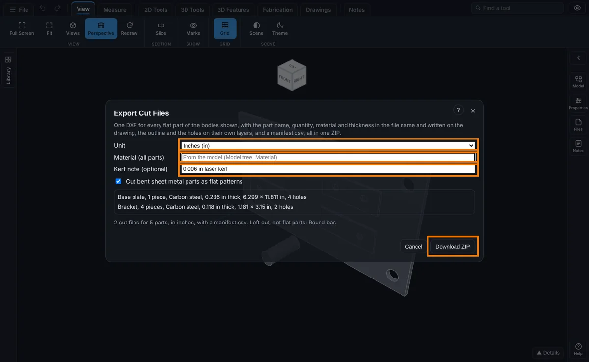
Options
- Unit: Millimeters (mm), Centimeters (cm), Meters (m) or Inches (in). Every file is written in that unit and says so, so your cutting program opens it at the right size. It starts on inches when your display unit is inches or feet, otherwise on your display unit.
- Material (all parts): one material name for every part. Empty means each part's own material (set in the Model tree, or read from the STEP file). Parts that are the same except for their material become one part when you type one name here.
- Kerf note (optional): up to 60 letters, written on every drawing as a KERF line and in the manifest. It is only a note: it never moves a line. To move the lines, use Offset for kerf and add lead-ins below.
- Offset for kerf and add lead-ins (plasma and laser): off unless you tick it, and on the Advanced plan and up. It moves every cut line half the Kerf toward the scrap (outlines outward, holes inward) and adds a Lead-in at each pierce, with an optional Lead-out. The boxes start at the usual plasma values (0.06 in kerf, 0.2 in lead-in, 0.1 in lead-out) converted to your unit. Leads start on a straight run away from corners: outside the part for an outline, inside the hole for a hole, as a quarter circle or a straight line. The size is how far the lead reaches from the cut line: a quarter circle of that radius, or a straight line at 45 degrees. A lead-out longer than the lead-in is cut down to it, and a hole too small for the kerf and a lead is pierced on its line (a note says so). They are on their own LEAD_IN and LEAD_OUT layers, and the outline and holes are written in cutting order (holes first, outline last). A hole too small for the kerf or a place with no room for a lead is listed under the file list, not hidden.
- Cut bent sheet metal parts as flat patterns: on by default. A body that is not a flat plate but is bent sheet metal is unfolded, with the bend allowance of the K-factor in the shop bend table, and its flat pattern is cut. Off leaves bent parts out.
What Is in the Files
- The file name: a number, the part name, the quantity, the material and the thickness, for example 02_Bracket_x4_Mild-Steel_0.25in.dxf. The number keeps the files in order and makes every name different.
- PARTS layer: the outer outline, as lines and true arcs, at true size, with its lower left corner at the origin.
- HOLES layer: every hole and cut-out of the part, so your cutting program can pierce them first. A round hole is a circle.
- LABELS layer: text below the part: PART, QTY, MATERIAL, THICKNESS and SIZE, and KERF when you typed a note. Turn the layer off before cutting. PARTS, HOLES and LABELS are the same layer names the nesting tool uses.
- manifest.csv: one row for each file: file, part, qty, material, thickness, unit, width, length, holes, cut_length, bends, kind (plate or flat pattern), bodies (the bodies that make up the quantity) and kerf_note. Open it in a spreadsheet to price the job or plan the cutting.
- Each file is DXF 2018, says its unit, its source and what it holds, and each part is seen from its largest flat face.
How Parts Are Found and Counted
- A flat part is a body whose largest flat face, pushed through the thickness, fills the body. A plate with holes, slots and a shaped outline is one. A block, a bar, a tube, a bolt or a plate with a block standing on it is not.
- Copies are counted: bodies with the same name, the same outline and holes to 0.05 mm, the same thickness and the same material are one part. A (2), <3> or :4 at the end of a name is ignored, and so is a number after a dash, an underscore or a space, so Bracket-1, Bracket_2 and Body 3 are named Bracket, Bracket and Body. Turning a copy, moving it or turning it over makes no difference. A part that stands alone keeps its number in the name.
- A mirror image is a different part, because a laser cuts only one hand: a left and a right bracket are two files.
- The quantity counts the bodies shown. A part that appears four times in an assembly is four bodies, so it comes out as x4.
Limits
- Only the bodies shown are read: at most 500 bodies, 600,000 triangles and 300 different parts, and 60 seconds to read them. Hide the fasteners of a large assembly first.
- Bodies from a mesh file (STL, OBJ, 3MF) have no faces to read and are left out.
- A thick plate whose thickness is more than half its shorter side is treated as a block and left out.
- The files hold outlines only: parts are not nested on a sheet here (use the nesting tool for that), no kerf offset is applied, and bends of a flat pattern are not drawn as bend lines.
- A file name holds the part name cut at 40 letters and the material cut at 20, with letters that file names do not allow changed to _.
- It needs the Advanced plan or higher, and on a shared model the Exports box ticked.
Common Mistakes and Messages
When something is wrong, the line under the list says why in words and Download ZIP is greyed out until it is put right.
- "None of the bodies shown is a flat plate or a sheet metal part, so there is nothing to cut." Show the plates and sheet metal parts. A solid block or a bar is not cut here.
- A part is missing from the list: it was left out because it is not flat. The line under the list names the bodies left out. A plate that looks flat but is thick (more than half its shorter side) counts as a block.
- Four copies come out as four files: their names (apart from a number at the end), materials or thicknesses differ, or one is a mirror image. Rename them the same in the Model tree, or give them the same material.
- "The kerf note is more than 60 letters. Make it shorter." Shorten the note.
- "... has an edge of ... points, more than the 500 one outline can be fitted from." That part has a very finely meshed edge (often a spline). Hide that body.
- "That is ... different parts, more than the 300 one export can hold." Hide some bodies and export the rest in a second ZIP.
- "There are ... bodies shown, more than the 500 one export can read." Hide some bodies and try again.
- "Reading the bodies took longer than 60 seconds" or "Fitting the outlines took longer than 60 seconds": hide some bodies, usually the fasteners, and try again.
- "This part has ... triangles, more than the 600,000 this export can read." Hide some bodies and try again.
- "No body is shown." Show a body in the Model tree, then open the window again.
- "This file is a 2D drawing already." A DXF, SVG or PDF is flat already.
- "Cut files on the Advanced plan or higher." The plan does not include exports.
- "The owner of this model has not allowed exports." The share does not have the Exports box ticked.
Tips
- Name your parts in the Model tree before you export: the names go in the file names.
- Check the first file in your cutting program against the part: the size line and the thickness must match.
- Send the ZIP as it is: the manifest.csv tells the shop what to cut, how many and in what.
- AI can make the same files: ask for cut files for the model and it uses the same tool.
Bent Parts
A part with bends also gets a layer named BEND in its DXF, holding the bend lines. They are for marking: do not cut them. The cut length does not count them. For the bend order and the flange lengths see Bend Sheet.